
An energy-saving liftable floating device

A lifting and energy-saving technology, applied to floating buildings, ships, etc., can solve the problems of fixing in the same place, difficulty in building houses on water, small space, etc., and achieve the effect of increasing flexibility

Inactive Publication Date: 2019-02-22
WUHAN UNIV OF TECH
View PDF4 Cites 0 Cited by
  • Summary
  • Abstract
  • Description
  • Claims
  • Application Information

AI Technical Summary

Problems solved by technology

[0003] At present, sea workers, marine product cultivators, recreational fishing enthusiasts and tourists and holiday enthusiasts often need to live on the water for a long time. Although the existing small boats can be helpful for water operations, because the space is too small, It is not suitable for long-term living due to poor wave resistance and other reasons, and there are also houses built on the water. However, the existing water houses are fixed with a number of columns in the water, and then a building platform is built on the columns, and finally built on the building platform. Build a house on the water, so it is difficult to build this kind of house on the water and the cost is too high. At the same time, this kind of house can only be fixed in the same place, causing a large gap between the sea water and the water surface when the sea tide ebbs, which is not easy to move. Great inconvenience for recreational fishing enthusiasts and tourism vacation enthusiasts

Method used


Image

  • An energy-saving liftable floating device
  • An energy-saving liftable floating device
  • An energy-saving liftable floating device

Examples


Embodiment 1

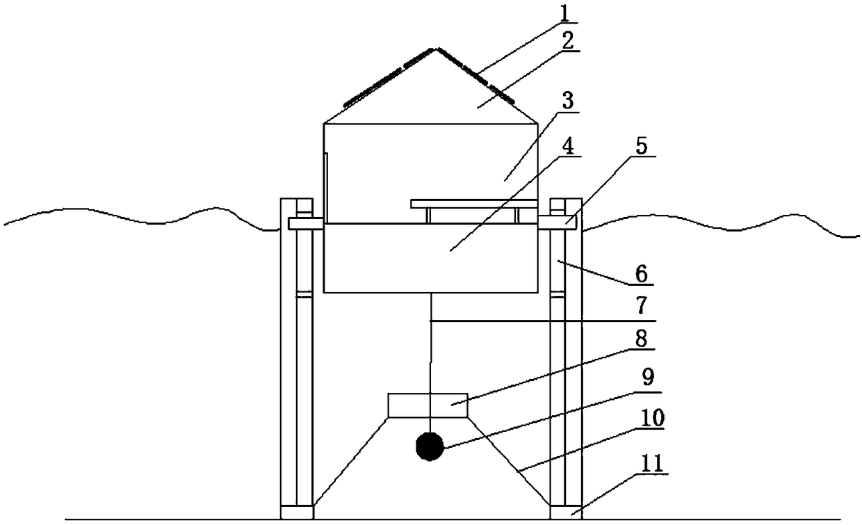
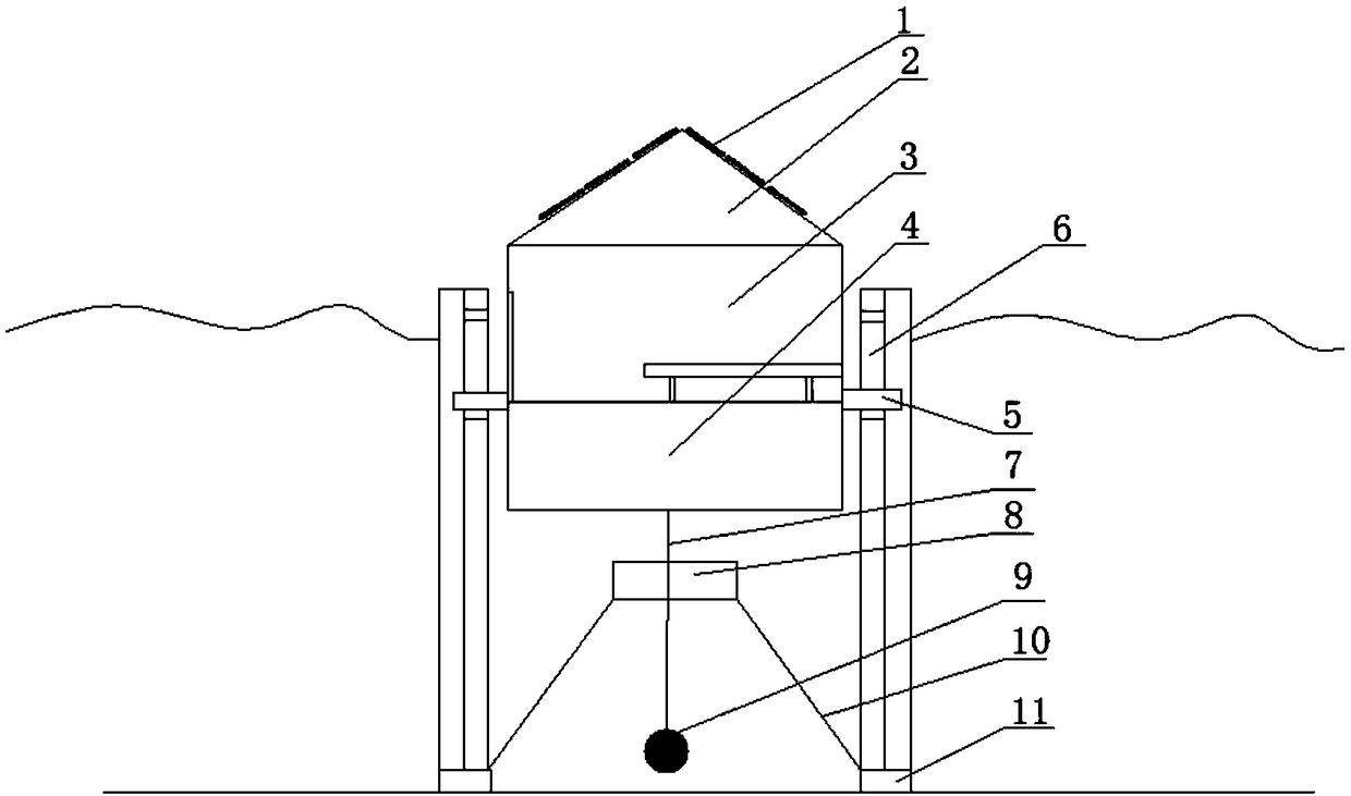
[0039] combine Figure 1 to Figure 4 As shown, the first embodiment provides an energy-saving liftable floating device, which includes: a floating platform, a guiding device and a stabilizing device.

[0040] Wherein, the floating platform has an upper rest cabin 3 and a lower water tank 4 (the upper rest cabin 3 and the lower water tank 4 are separated by a partition); the upper rest cabin 3 is provided with a roof structure 2, and the roof structure 2 is provided with a photovoltaic power generation system 1, the photovoltaic power generation system 1 is used to provide electric energy for the internal electronic components of the upper rest cabin 3, and has the function of environmental protection and energy saving; the bottom of the lower water tank 4 is provided with an openable A combined hatch, which is used to bring external water into the lower water tank 4 when the hatch is opened, so that at least a part of the upper rest cabin 3 is submerged into the water, and the...

Embodiment 2

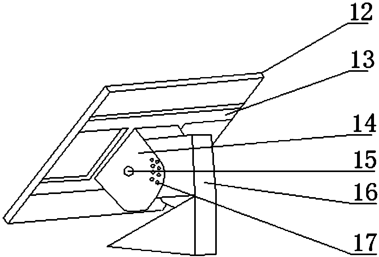
[0056] combine Figure 1 to Figure 5 As shown, the second embodiment is further refined on the basis of the first embodiment, mainly aiming at the improvement of the movable lighting element. Of course, the second embodiment includes the technical content disclosed in the first embodiment, and the same technical content as the first embodiment will not be repeated. The differences between the second embodiment and the first embodiment will be described below.

[0057] The internal electronic components of the floating platform include: a movable lighting element, the lighting element has a moving handle, and the moving handle is installed on the side wall of the upper rest cabin 3 through a magnetic adjustment seat. As a further technical solution, the moving handle has a convex ball head, and the surface of the convex ball head is provided with a metal coating; the magnetic adjustment seat has a concave joint, and the concave joint has a magnetic coating.

[0058] Specifical...

Embodiment 3

[0062] Of course, in order to cooperate with the use of this energy-saving liftable floating device, some innovative auxiliary mechanisms can be added, such as: heating at night in winter, or equipment such as food barbecue. In order to ensure the flexibility and portability of the equipment, the upper rest cabin 3 of the energy-saving liftable floating equipment is also equipped with a disposable portable paper oven. Tin foil paper is attached, and a heat insulation layer is arranged on the bottom and surroundings of the inner cavity of the furnace body, barbecue charcoal is placed on the bottom heat insulation layer, and a barbecue rack is set at the opening of the upper part of the furnace body.

[0063] Preferably, the manufacturing method of the disposable portable paper oven includes:

[0064] S1. Main production:

[0065] S11. Prepare a square first cardboard, mark the length quarters L1, L2, L3 along the length direction of the first cardboard, and mark the width quar...


PUM


Abstract

The invention relates to the technical field of water energy-saving facilities, in particular to energy-saving type liftable floating equipment and specifically to energy-saving type liftable floatingequipment capable of being used for places such oceans and lakes. The energy-saving type liftable floating equipment comprises a floating platform, a guiding device and a stabilizing device; and by using the stabilizing device, the integral structure of the energy-saving type liftable floating equipment is more stable, the anti-wave performance of a water house is improved, and the shaking influence on the integral structure during the moving of personnel is also reduced. By using a photovoltaic power generation system, an environment-friendly and energy-saving effect is realized. And moreover, the energy-saving type liftable floating equipment can synchronously rise with the water level and can also control itself to automatically lift so that the flexibility of the water house is improved. The energy-saving type liftable floating equipment has the advantages that the structure is simple, the design is reasonable, the making cost is low, the stability is high, the use is convenient,the anti-wave performance is good, the shock resistance is good, the energy-saving type liftable floating equipment can freely move in the water, the energy-saving type liftable floating equipment isenergy-saving and environment-friendly, and the energy-saving type liftable floating equipment is beneficial for popularization and application.

Description

technical field [0001] The invention relates to the technical field of water energy-saving facilities, in particular to an energy-saving liftable floating device, in particular to an energy-saving liftable floating device that can be used in oceans, lakes and other places. Background technique [0002] As we all know, with the advent of the world energy crisis, the development, utilization and promotion of renewable resources has become a very urgent mission for mankind. Under the current technological conditions, if wind energy and solar energy are closely combined with people's food, housing, and transportation to make a device, it will definitely optimize the structure of human life and alleviate the energy crisis. [0003] At present, sea workers, marine product cultivators, recreational fishing enthusiasts and tourists and holiday enthusiasts often need to live on the water for a long time. Although the existing small boats will help in water operations, but because the...

Claims


Application Information

Patent Timeline
Patent Type & Authority Patents(China)
IPC IPC(8): B63B35/44
CPCB63B35/44B63B2035/4426B63B2035/4453
Inventor 胡宇康
Owner WUHAN UNIV OF TECH
Learn More