
Combined electric appliance fixing seat with wire inlet device

A combined and fixed seat technology, which is applied in the direction of electrical components, supporting machines, and non-rotating vibration suppression, can solve the problems of reducing the service life of electrical appliances, wasting money, and easily breaking wires due to extrusion, so as to reduce vibration energy and reduce vibration. Negative effects, the effect of easy removal and installation

Inactive Publication Date: 2018-09-04
瑞普兰德电梯有限公司
View PDF0 Cites 3 Cited by
  • Summary
  • Abstract
  • Description
  • Claims
  • Application Information

AI Technical Summary

Problems solved by technology

[0003] Electrical appliances will vibrate during the working process, especially for larger electrical appliances. In the case of long-term use, the vibration will have an impact on the electrical appliances themselves. The existing electrical fixtures have the following disadvantages: First, the bearing area of ​​the fixtures Limited, it can only be used for electrical appliances within the bearing area. If there are many electrical appliances with different models and sizes, multiple electrical appliance fixing seats are required, which not only takes up space but also wastes money; second, the fixing seats are generally not installed There is a wire inlet device, and the electrical appliances with wires installed at the bottom are often easily squeezed and broken when placed on the fixed seat, which increases the cost of maintenance and reduces the service life of the electrical appliances

Method used


Image

  • Combined electric appliance fixing seat with wire inlet device
  • Combined electric appliance fixing seat with wire inlet device
  • Combined electric appliance fixing seat with wire inlet device

Examples


Embodiment Construction

[0027] In order to make the technical means, creative features, objectives and beneficial effects realized by the present invention easy to understand, the present invention will be further described below in conjunction with specific embodiments.

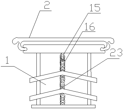
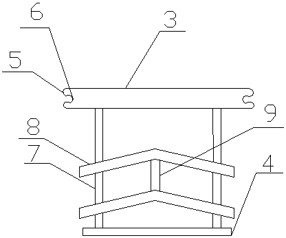
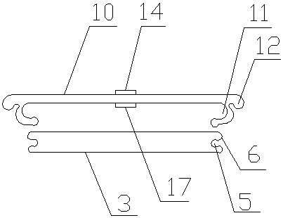
[0028] A combined electric appliance fixing seat with a wire entry device, the specific embodiment of which is: a support seat 1, a base body 2 and a line entry device, the support seat 1 is arranged under the base body 2, and the support seat 1 includes The detachable upper support plate 3, the lower support plate 4 and two sets of support assemblies, the two sides of the upper support plate 3 are provided with chute 5 transversely, and the upper edge of the chute 5 is set along the opening direction of the chute 5 There is a first protrusion 6, and the support assembly includes four support rods 7 and L-shaped connecting plates 8, and the upper and lower ends of two adjacent supporting rods 7 are respectively connected by the L-sh...


PUM


Abstract

The invention relates to a combined electric appliance fixing seat with a wire inlet device. The combined electric appliance fixing seat comprises a support seat, a base body and the wire inlet device, wherein the support seat comprises a detachable upper support plate, a lower support plate and two groups of support assemblies, chutes are formed in both sides of the upper support plate in a transverse direction, first bulges are arranged on the upper edges of the chutes in the forming direction of the chutes, and the support assemblies comprise four support rods and L-shaped connecting plates; the base body comprises a plurality of bottom plates, first round holes are formed in the middle of the bottom plates, an upper pressing plate is arranged above the first round holes, a sleeve is installed below the first round holes, a first damping spring sleeves the sleeve, and a lower pressing plate which is the same as the inside diameter of the sleeve is arranged in the middle of the uppersupport plate; and the wire inlet device comprises a boss arranged on the lower support plate and a containing cavity formed in the middle of the boss, and a wire and cable clip is arranged in the containing cavity. The combined electric appliance fixing seat has the advantages of the simple structure, easiness in removal and installation and good damping effect and is suitable for electric appliances of different sizes, less space is occupied after retraction, and electric appliance wires are safely arranged.

Description

technical field [0001] The invention belongs to the technical field of electric appliance support structures, and in particular relates to a combined electric appliance fixing seat with a wire inlet device. Background technique [0002] With the improvement of people's living standards, people have more and more demands for various electrical equipment in daily life and production. The use of electrical appliances not only provides convenience for people's lives, but also creates great economic benefits. Advanced Electrical appliances increase labor productivity, reduce labor intensity, improve the production environment, and complete work beyond the scope of manpower. As one of the foundations of national production and life, electrical appliances have a direct and important impact on the entire social life and the development of the national economy. [0003] Electrical appliances will vibrate during the working process, especially for larger electrical appliances. In the ...

Claims


Application Information

Patent Timeline
Patent Type & Authority Applications(China)
IPC IPC(8): F16M11/04F16F15/04H02G3/04
CPCF16M11/04F16F15/04H02G3/0437
Inventor 王羽丁鹏
Owner 瑞普兰德电梯有限公司
Learn More