
Downhole tool member for hydrocarbon resource recovery

a technology of hydrocarbon resource recovery and tool member, which is applied in the direction of sealing/packing, chemistry apparatus and processes, and well accessories. it can solve the problems of difficult to accurately evaluate the degradation behavior of degradable polymer, and the mechanical strength and time to collapse technology of such a downhole tool member has not been satisfactorily developed, so as to achieve accurate design of degradation characteristics

Active Publication Date: 2015-10-15
KUREHA KAGAKU KOGYO KK
View PDF4 Cites 5 Cited by
  • Summary
  • Abstract
  • Description
  • Claims
  • Application Information

AI Technical Summary

Benefits of technology

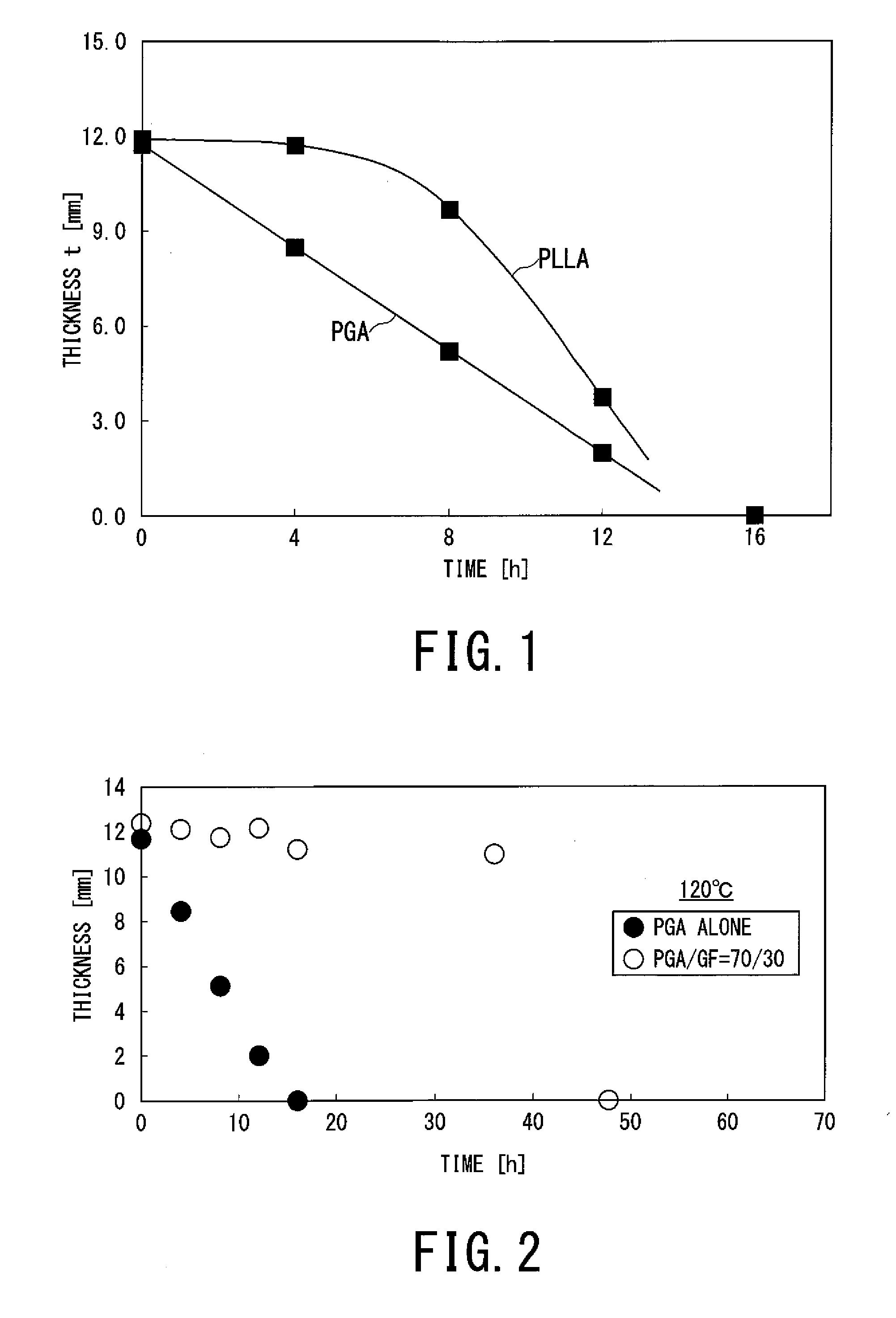
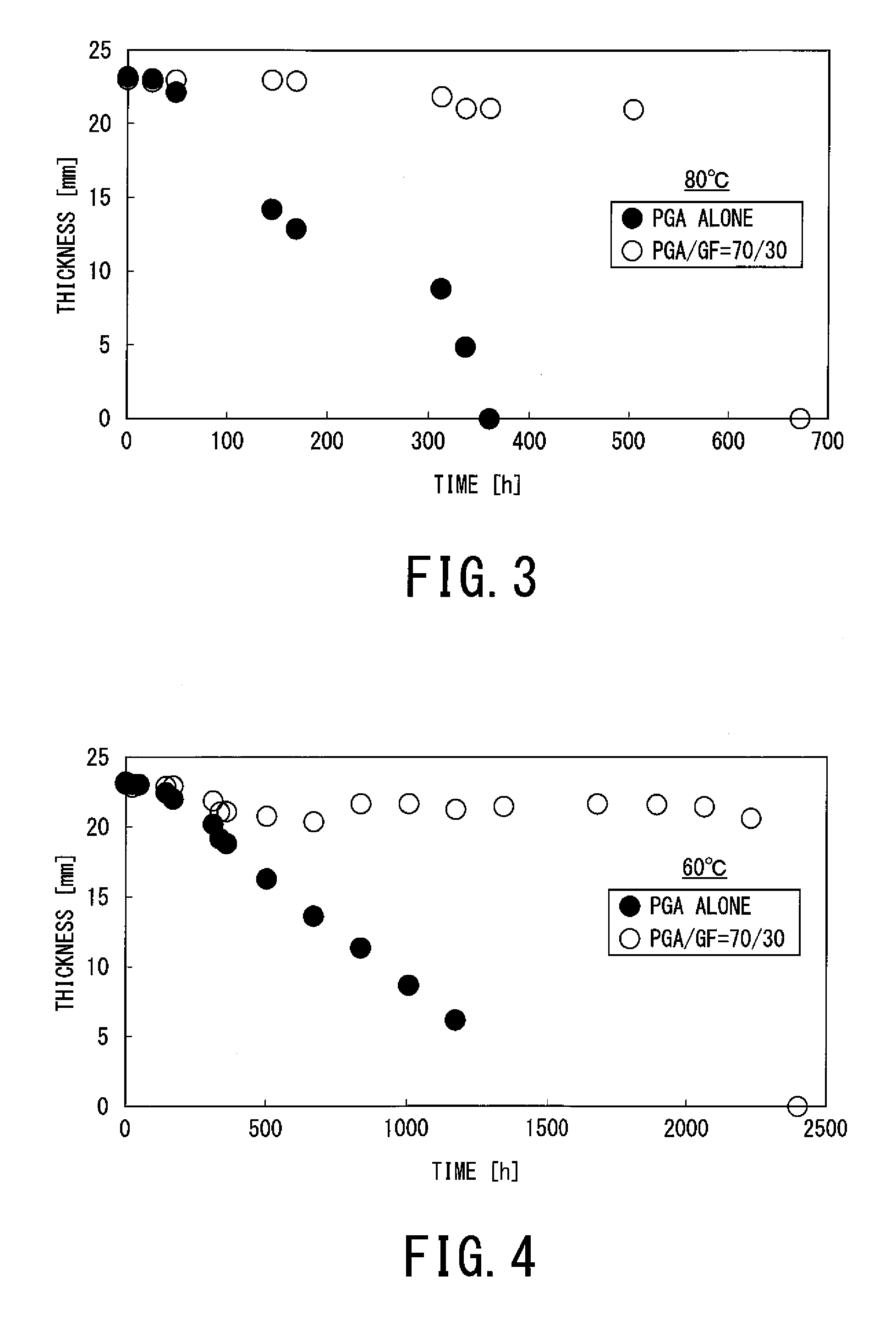
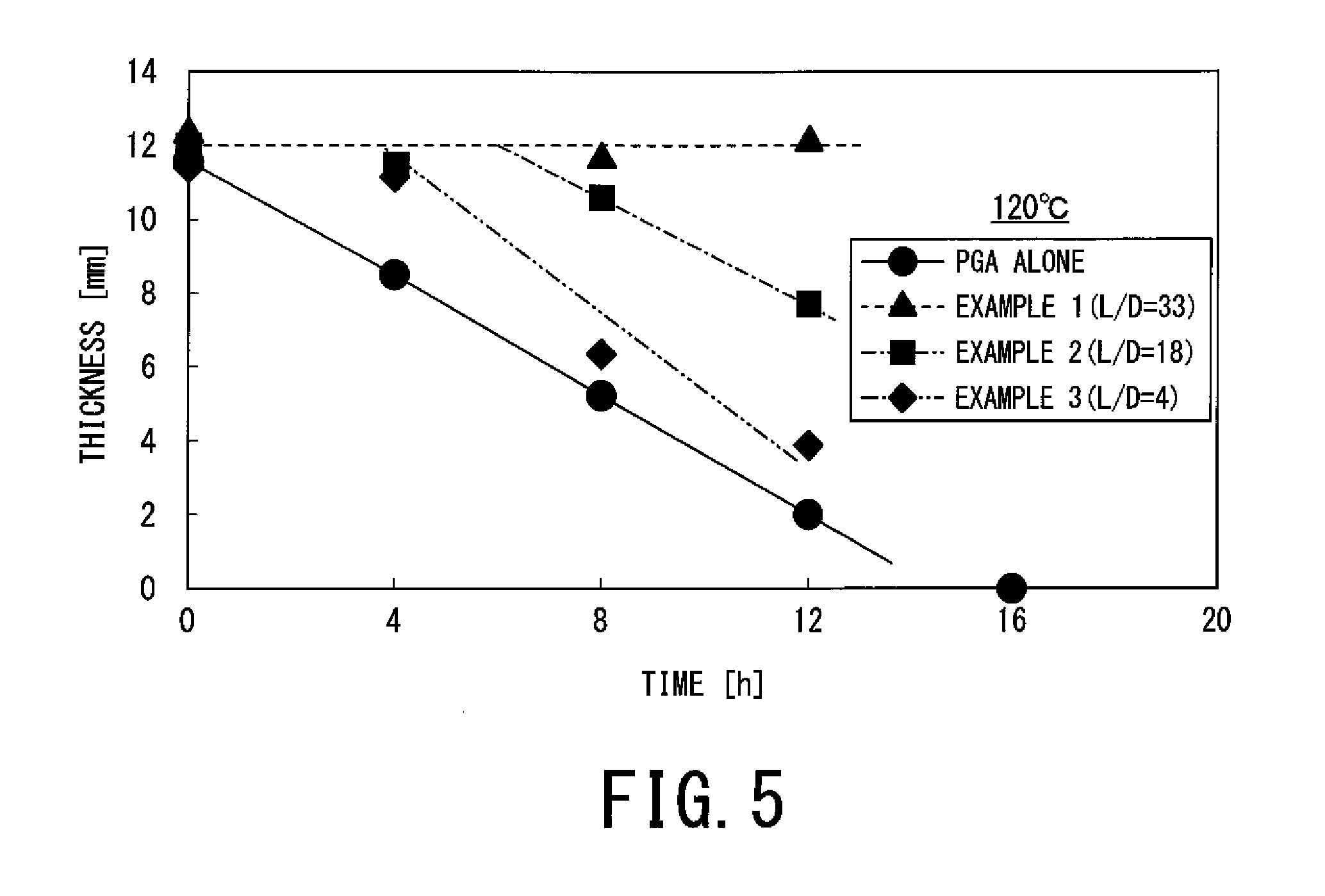
The present invention relates to a downhole tool member for hydrocarbon resource recovery. The member is made of a polyglycolic acid resin blended with a short fiber reinforcement material. The resulting tool member has a suppressed initial thickness reduction rate but a fast terminal thickness reduction rate. By controlling the aspect ratio of the reinforcement material, the suppression period of the initial thickness reduction rate can be controlled. The tool member is thus designed to have the required strength and retention time for its use as a packing or sealing member, and to show a reduced deformability during finite working hours and quick collapsing after the operation.

Problems solved by technology

However, the technology of designing the mechanical strength and time to collapse of such a downhole tool member by using such a degradable polymer has not satisfactorily developed.
This is because it was difficult to accurately evaluate the degradation behavior of the degradable polymer.

Method used


Image

  • Downhole tool member for hydrocarbon resource recovery
  • Downhole tool member for hydrocarbon resource recovery
  • Downhole tool member for hydrocarbon resource recovery

Examples


example 1

Compounding Conditions

[0056]PGA alone (Mw (weight average molecular weight)=200,000, made by Kureha Corp.) and glass fiber (GF) bound with a mixture of urethane resin and epoxy resin (“GL-HF”, made by Owens Corning Co.; shorter-axis diameter: 10 μm and fiber length: 3 mm) were supplied in a weight ratio of 70 / 30 by a feeder to a twin-screw extruder (“2D25S”, made by Toyo Seiki Seisakusyo, Ltd.) and extruded through a screw with a full-flight structure at an extrusion temperature of 250° C. to prepare pellets (diameter: about 3 mm, length: about 3 mm) through a pelletizer. As a result, compound pellets containing GF short fiber with an aspect ratio of 33 were obtained. The molecular weight of the compound pellets was measured at 180,000.

example 2

[0057]Pellets were prepared in the same manner as in Example 1 except for changing the screw structure of the twin-screw extruder so as to apply a shearing force during kneading, followed by extrusion. The pellets were found to contain GF fiber with an aspect ratio of 18.

example 3

[0058]Pellets were prepared in the same manner as in Example 1 except for using milled glass fiber (“EFH50-31”, made by Central Glass CO., Ltd.; shorter-axis diameter: 11 μm and fiber length: 50 μm) as the glass fiber (GF). The aspect ratio of the GF short fiber was calculated at 4 from the maker's nominal values.


PUM

PropertyMeasurementUnit
diameteraaaaaaaaaa
aspect ratioaaaaaaaaaa
temperaturesaaaaaaaaaa

Abstract

A downhole tool member for hydrocarbon resource recovery, comprising a shaped body of a polyglycolic acid resin blended with an inorganic or organic short fiber reinforcement material, and having thickness reduction rate characteristics when held in water at 120° C., inclusive of: an initial thickness reduction rate (as an average for a holding period for 4 hours) which is at most 0.8 times that of a shaped body of the polyglycolic acid resin alone, and has a terminal thickness reduction rate (after the thickness decreases to 50% or less of an initial thickness) which is larger than 1.5 times the initial thickness reduction rate. As a result, it is possible to provide a downhole tool member, that is a temporary tool for formation or repair of downholes for recovery of hydrocarbon resources including oil and gas, or a part of the tool, which allows more accurate designing of collapse characteristics thereof.

Description

TECHNICAL FIELD[0001]The present invention relates to a member which forms a tool per se or a component thereof for formation or repair of downholes for recovery of hydrocarbon resources including oil and gas.BACKGROUND ART[0002]Downholes (underground drilling pits) are prepared for recovery of hydrocarbon resources including oil and gas (representatively called “oil” sometimes hereafter) from the underground, and tools for the formation or repair of the downholes, such as frac plugs (disintegratable plugs), bridge plugs, cement retainers, perforation guns, ball sealers, sealing plugs and packers (inclusively referred to as “downhole tools” hereafter), are used and thereafter disintegrated or allowed to fall down without recovery thereof onto the ground as they are in many cases. (Examples of such downhole tools and manners of use thereof are illustrated in, e.g., Patent documents 1-5). Therefore, about the tool of such temporary use, it has been recommended to form the whole or a c...

Claims


Application Information

Patent Timeline
Patent Type & Authority Applications(United States)
IPC IPC(8): E21B33/12
CPCE21B33/12C08L67/04C08L2205/03C08L2205/035C08L2205/16C08L75/04C08L63/00C08K7/14C08K7/06C08L77/10C08K9/08C08K2201/003C08K2201/016E21B33/1208C09K8/88C08K7/02C08L67/02
Inventor OKURA, MASAYUKISAIJO, HIKARUYOSHIDA, KATSUMISATO, HIROYUKI
Owner KUREHA KAGAKU KOGYO KK
Learn More