Multi-instruction switch

Active Publication Date: 2006-12-05
ZIPPY TECH
View PDF7 Cites 26 Cited by
  • Summary
  • Abstract
  • Description
  • Claims
  • Application Information

AI Technical Summary

Benefits of technology

[0005]Therefore the primary object of the present invention is to provide a multi-instruction switch that can generate a plurality of circuit signals.
[0006]To achieve the foregoing object, the multi-instruction switch according to the invention includes a control disk, an anchor member and a depressing element. The control disk can drive a first conductive element to rotate relative to the anchor member. The anchor member has a terminal connector which includes a common terminal, a first terminal, at least one second terminal and a third terminal. There is a second conductive element located beneath the depressing element that can move up and down relative to the depressing element to connect a circuit. The first conductive element has a plurality of contact arms mating the terminal connector. One of the contact arms is connected to the common terminal in normal conditions. Other contact arms are connected alternately to contact zones and non-contact zones of the first and second terminals to generate a plurality of signals. By pressing the depressing element to connect the common terminal and the third terminal, the signals can be output. Thus one signal switch can execute a plurality of actions. The structure is compact and simple.
[0007]According to another embodiment of the invention, an accurate positioning adjustment design is provided. There is an anchor bar located beneath the control disk that has a bent portion in the middle section. The anchor member has guiding notches on the perimeter corresponding to the bent portion. By rotating the control disk according to preset marks formed thereon, anchoring position can be accurately adjusted and set to issue correct commands. It also provides an improved click feeling.

Problems solved by technology

The product adopted such a rotary switch cannot be shrunk as desired.
Moreover, it consists of too many elements.
Fabrication and assembly are more difficult, and production cost is higher.

Method used


Image

  • Multi-instruction switch
  • Multi-instruction switch
  • Multi-instruction switch

Examples


Embodiment Construction

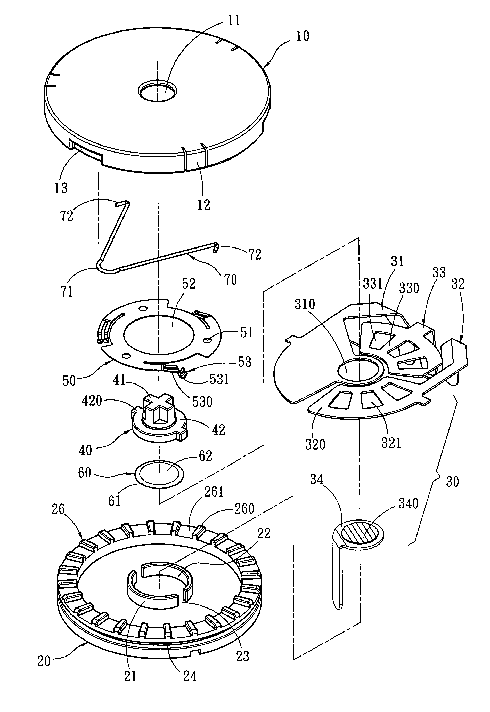
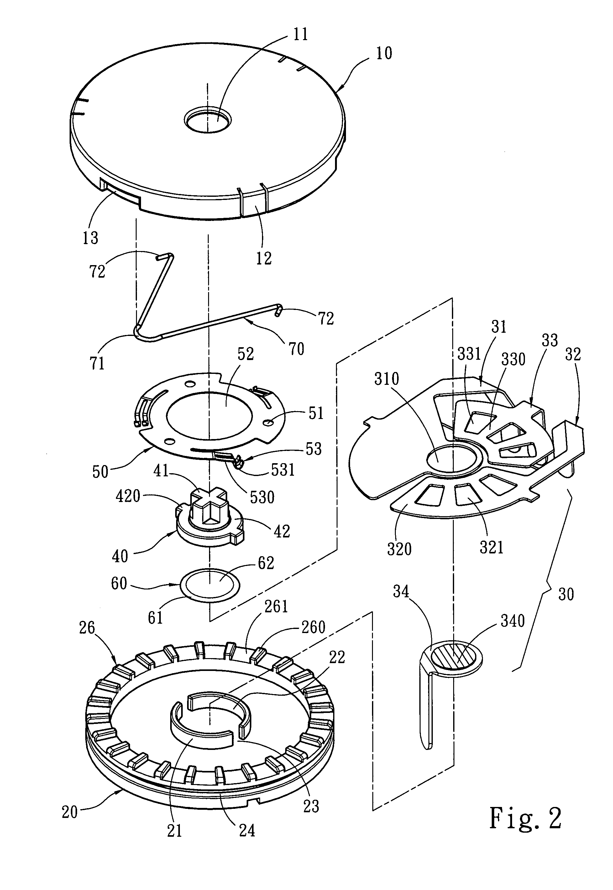
[0018]Please refer to FIGS. 1, 2 and 3 for an embodiment of the multi-instruction switch of the invention. It includes a control disk 10, an anchor member 20 which contains a terminal connector 30 and a depressing element 40.

[0019]The control disk 10 has an opening 11 on an upper side to hold the depressing element 40, a plurality of coupling portions 12 on the perimeter that are movable. Each of the coupling portions 12 has a retaining portion 120 for coupling the control disk 10 on an upper side of the anchor member 20. The perimeter of the control disk 10 further has a plurality of recesses 13 for coupling with external elements.

[0020]The anchor member 20 has a protrusive detent portion 21 in the center which has an anchor trough 22 and two notches 23 on two sides of the anchor trough 22. The depressing element 40 and a second conductive element 60 are held and anchored in the anchor trough 22. The anchor member 20 further has an annular groove 24 on the perimeter to couple with ...


PUM


Abstract

A multi-instruction switch includes a control disk, an anchor member and a depressing element. The control disk can drive a first conductive element to rotate relative to the anchor member. The anchor member has a terminal connector which includes a common terminal, a first terminal, at least one second terminal and a third terminal. A second conductive element located beneath the depressing element can move up and down relative to the depressing element to connect a circuit. The first conductive element has a plurality of contact arms mating the terminal connector. One of the contact arms is connected to the common terminal in normal conditions. Other contact arms are connected alternately to contact zones and non-contact zones of the first and second terminals to generate a plurality of signals. By pressing the depressing element to connect the common terminal and the third terminal, the signals can be output.

Description

FIELD OF THE INVENTION[0001]The present invention relates to a switch and particularly to a multi-instruction switch with rotation instructions and pressing instructions.BACKGROUND OF THE INVENTION[0002]Multi-instruction switch is widely used now in various information appliances (IAs) such as mobile phones, PDAs, computer keyboards and the like. The multi-instruction switch can provide electric connection in multiple stages and generate a plurality circuit signals, hence a single switch can execute multiple actions to reduce the size of the information products. Utilization also is more convenient.[0003]U.S. Pat. Nos. 6,236,002 B1 and 6,262,378 B1 disclose a rotary switch which includes a rotary dial, a binding member to hold the rotary dial, a rotary plate located in the binding member and coupled with the rotary dial to be driven thereof, and a housing coupled with the binding member. The housing has a common terminal and a first contact and a second contact that contain a plural...

Claims


Application Information

Patent Timeline
IPC IPC(8): H01H9/00
CPCH01H19/11H01H19/585H01H25/06
Inventor SU, TSUI-JUNGCHEN, YUN-CHENLEE, HONG-YI
Owner ZIPPY TECH
Why Eureka
Try Eureka