
Automatic reference voltage trimming technique

Active Publication Date: 2006-12-07
MICROCHIP TECH INC
View PDF25 Cites 24 Cited by
  • Summary
  • Abstract
  • Description
  • Claims
  • Application Information

AI Technical Summary

Benefits of technology

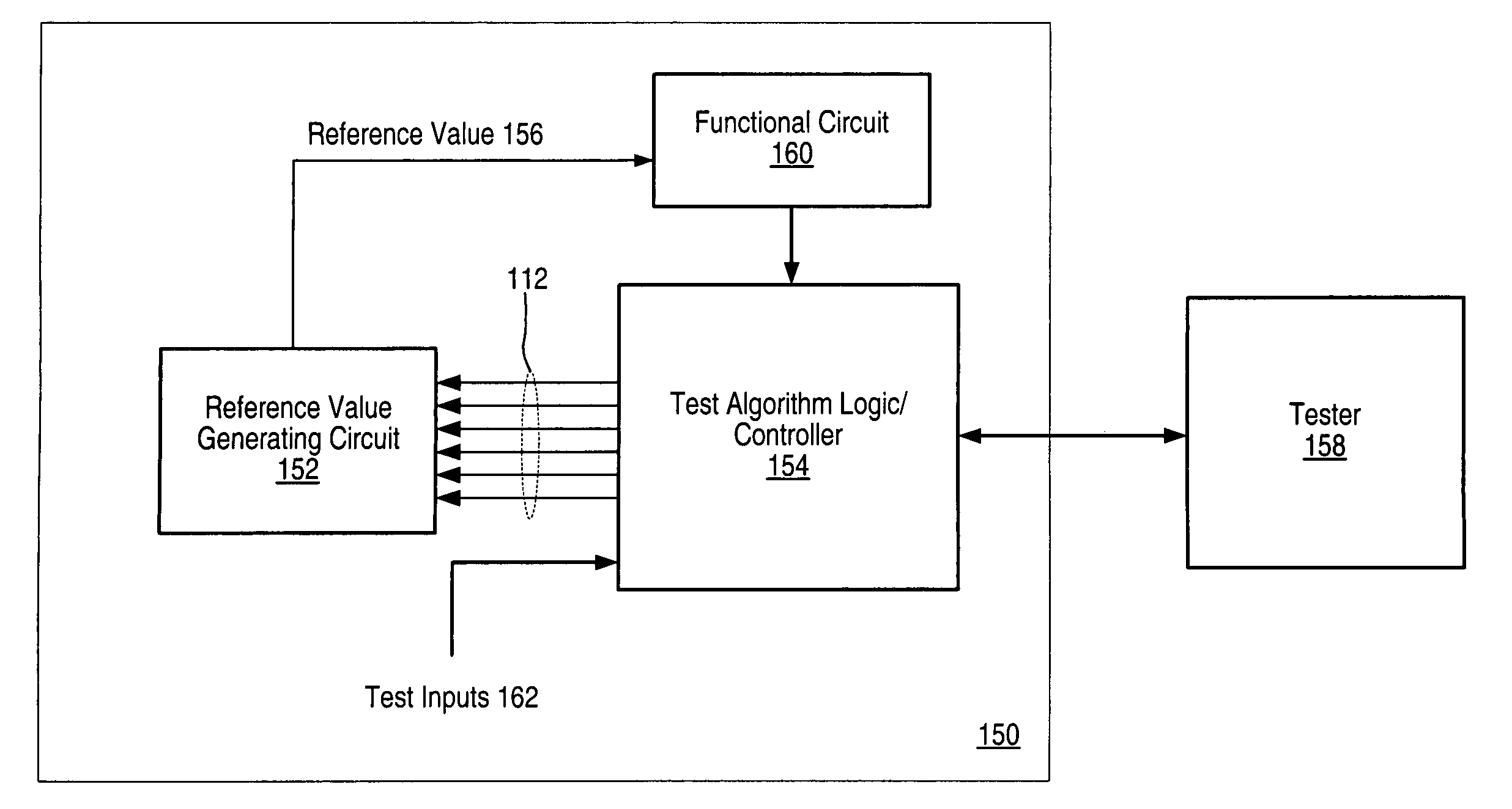
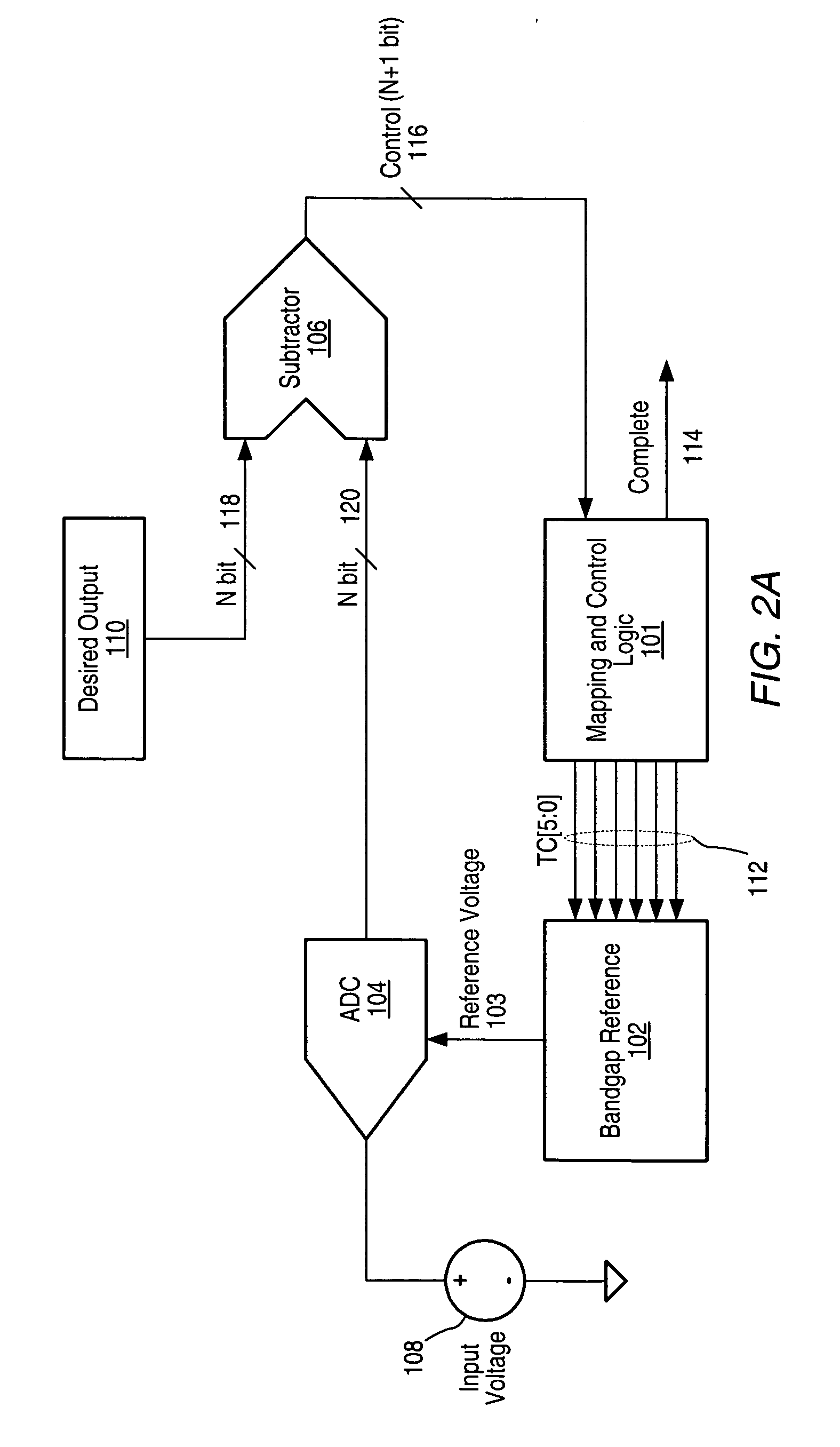
[0010] In one set of embodiments, the invention comprises a system and method for performing auto-trimming of a voltage reference comprised on an integrated circuit (IC). The trimming of the reference, which may be a bandgap reference, may be controlled by an algorithm executed by logic circuitry also configured on the IC. The bandgap reference may be configured to generate a reference voltage provided to an analog to digital converter (ADC) comprised in a temperature sensor that may also be configured on the integrated circuit. The logic circuitry may be configured to execute one or more of a variety of test algorithms, for example a Successive Approximation Method or Remainder Method, that are operable to adjust values of reference trim bits used in trimming the bandgap reference. Alternate embodiments may include different algorithms, which may be used to control the automatic trimming process. A tester system configured to perform testing of the integrated circuit may initiate execution of the test algorithm, thereby initiating the trimming process, and may wait for the test algorithm to complete within a previously defined amount of time, or may poll the logic circuitry to determine when the trimming process is complete. This may free the tester from controlling the trim operation.
[0014] Alternately, simple logic operations may be performed on the remainder such that the result of the logic operations is the value latched into the trim bits. For example, the difference value may need to be changed to a two's complement number. These logic operations may be required to allow proper design of the trim network in situations where direct mapping of the remainder to the trim bits may be impractical. Furthermore, during the logic operations, the trim bit setting used to correct the error may be selected so as to take into account both the value of the remainder and the bit setting that produced the remainder. In this way, the logic operations may be repeated, that is, another comparison of the actual value may be made against the ideal value after all the trim bits have been set, and the remainder may again be calculated as the difference value resulting from the comparison. The new remainder may then be used, along with the bit setting that created the remainder, to calculate a new, more accurate, setting of the trim bits.
[0015] Various algorithms may thus be implemented with on-chip logic circuits that free the tester from having to control the trim algorithm, with all the attendant benefits. In some embodiments, the resulting time and cost for trimming may be lower for the Remainder Method than for a Successive Approximation Method using one comparison per bit.

Problems solved by technology

If the measurement is too low, the MSB may remain turned off.

Method used


Image

  • Automatic reference voltage trimming technique
  • Automatic reference voltage trimming technique
  • Automatic reference voltage trimming technique

Examples


Embodiment Construction

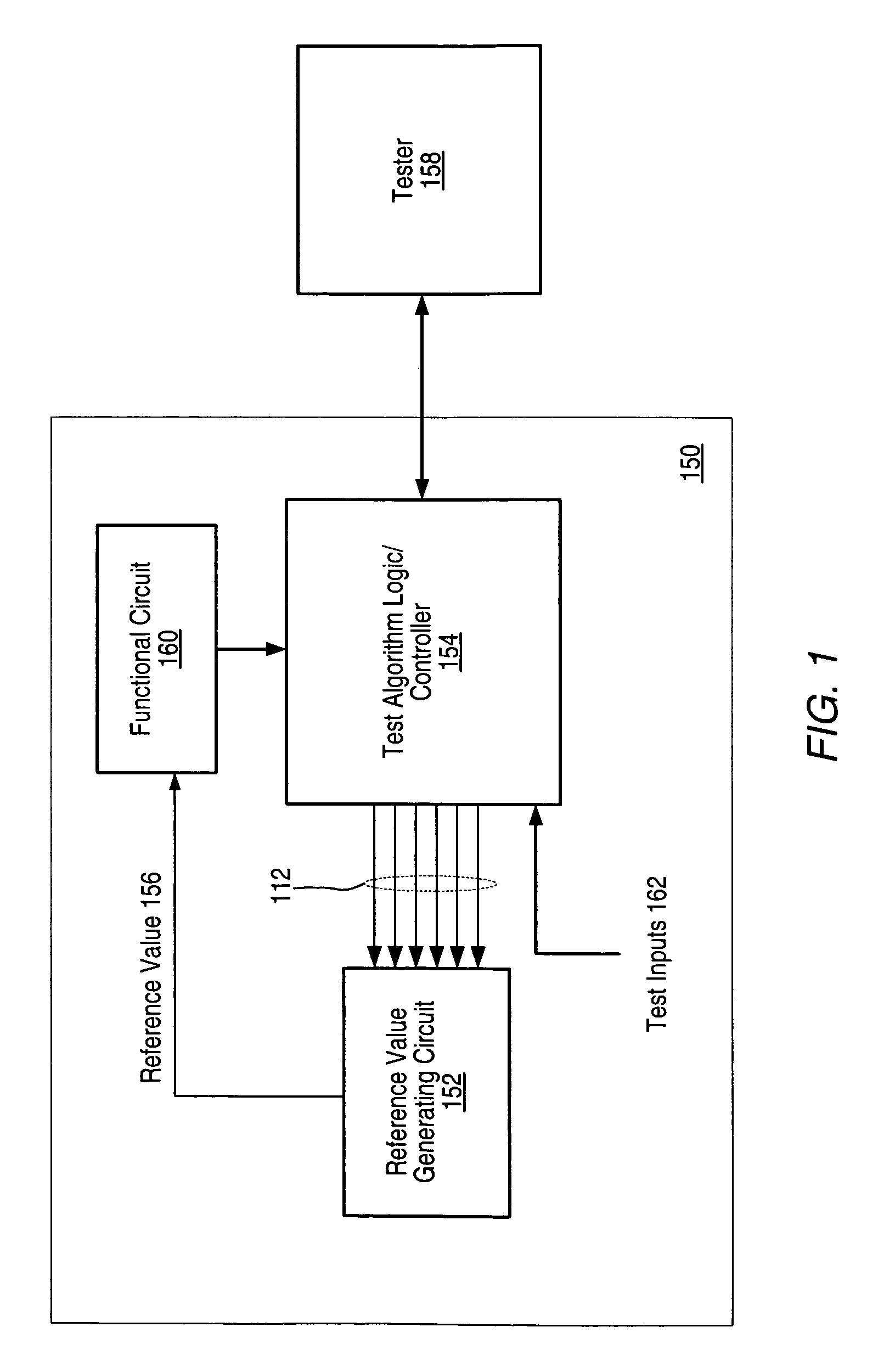
[0027]FIG. 1 shows one embodiment of an integrated circuit (IC) 150 in which a controller / logic block (LBC) 154 is configured to perform a test algorithm to control trimming of a reference value generating circuit (RGC) 152 in order to obtain a specific reference value 156. Reference value 156 may be used by functional circuit (FC) 160, which is also comprised on IC 150. LBC 154 may be configured to receive one or more test inputs 162 and one or more control signals from FC 160. LBC 154 may also be configured to communicate with a tester apparatus 158, which may initiate execution of the test algorithm by LBC 154 and may poll LBC 154 to ascertain whether trimming has been completed. Alternately, LBC 154 may be designed to provide a signal to tester apparatus 158 a specified time period after testing had been initiated, indicating that the trimming is complete. In one embodiment, RGC 152 is bandgap reference and reference value 156 is a reference voltage, while FC 160 is an ADC opera...


PUM


Abstract

In one set of embodiments, trimming of a reference, which may be a bandgap reference and which is configured on an integrated circuit, may be controlled by an algorithm executed by logic circuitry also configured on the integrated circuit. The bandgap reference may be configured to generate a reference voltage provided to an analog to digital converter (ADC) comprised in a temperature sensor that may also be configured on the integrated circuit. The logic circuitry may be configured to execute one or more of a variety of test algorithms, for example a Successive Approximation Method or remainder processing, that are operable to adjust values of reference trim bits used in trimming the bandgap reference. A tester system configured to perform testing of the integrated circuit may initiate execution of the test algorithm, thereby initiating the trimming process, and may wait for the test algorithm to complete within a previously defined amount of time, or may poll the logic circuitry to determine when the trimming process is complete.

Description

BACKGROUND OF THE INVENTION [0001] 1. Field of the Invention [0002] This invention relates generally to the field of analog integrated circuit design and, more particularly, to the design of reference voltage control circuits. [0003] 2. Description of the Related Art [0004] In the design of many integrated circuits, more specifically those using complementary metal-oxide-semiconductor (CMOS) technology, a specified and stable reference value, for example a reference voltage, may often be required to insure proper circuit operation. When designing analog circuits or circuit with analog components, a specified and stable reference voltage may be a necessity for the circuit to properly function in a substantially predictable manner. Examples of such circuits include devices that monitor temperature and voltage. Temperature monitoring devices are often included as part of digital systems, especially systems that include high-performance, high-speed circuits prone to operational variance...

Claims


Application Information

Patent Timeline
IPC IPC(8): G06F19/00
CPCG01R31/31703G01R31/3167
Inventor ANDERSON, THOMAS R.CASTELLANO, WILLIAMMCLEOD, SCOTT C.
Owner MICROCHIP TECH INC
Learn More