
Modular LRU accessory mounting substrate for auxiliary power unit

Inactive Publication Date: 2007-02-08
HAMILTON SUNDSTRAND CORP
View PDF6 Cites 24 Cited by
  • Summary
  • Abstract
  • Description
  • Claims
  • Application Information

AI Technical Summary

Benefits of technology

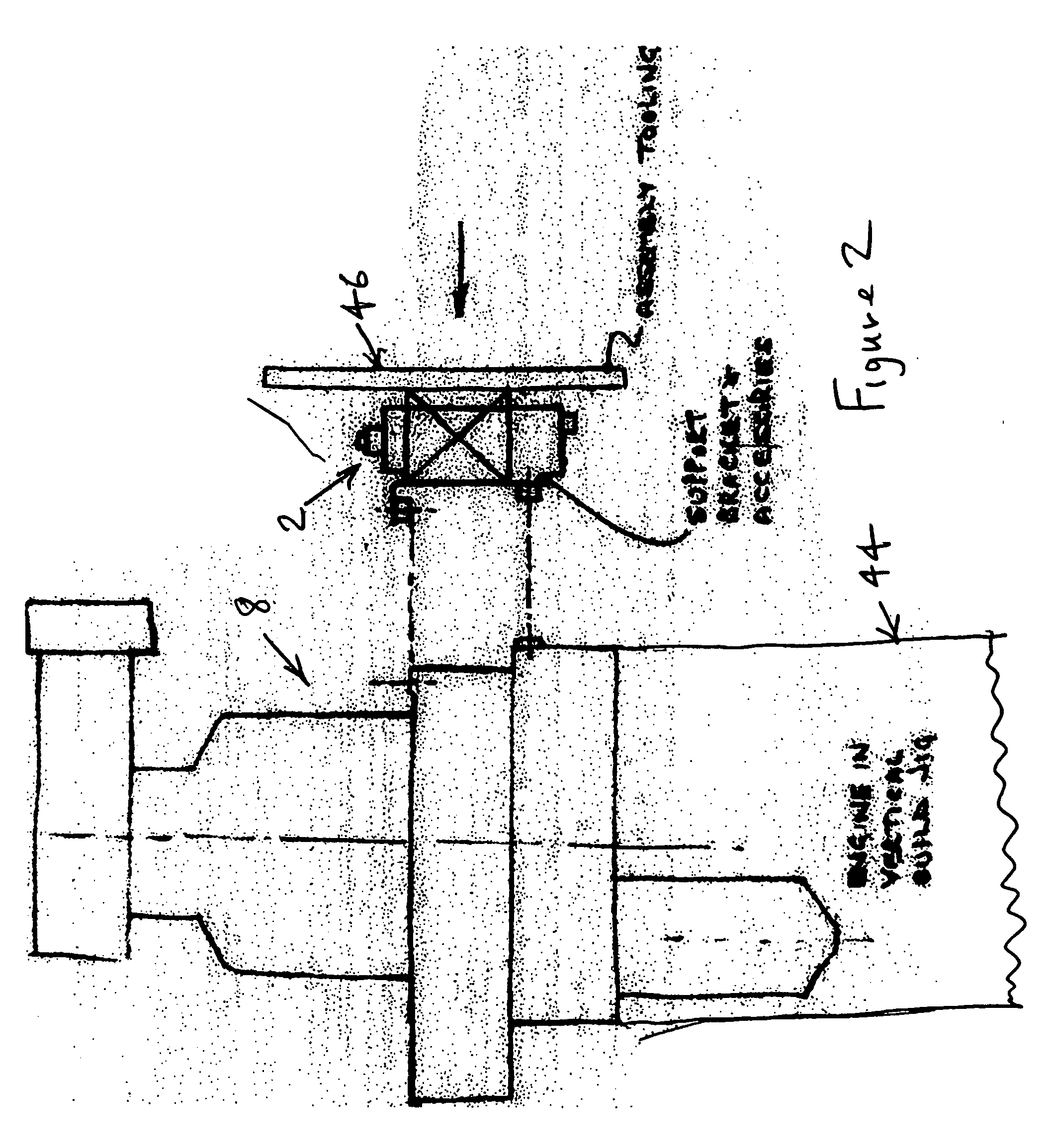
[0003] The invention comprises a special multiple accessory support bracket that serves to support and mount many or all of the external accessory components, such as LRUs, tubes and electrical harnesses that connect to the APU to facilitate installation of the components onto the accessory support bracket before installation of the accessory support bracket on the APU. The multiple accessory support bracket preferably has its own vibration isolators that serve to provide all components that are mounted to it. Since all the external accessories then install on to the APU as a single pre-assembled unit, this configuration reduces the number of parts needed for assembly, thereby reducing inventory and cost. A mounting tool may be used to conveniently attach and remove the multiple accessory support bracket with all associated components mounted to it, thereby further reducing assembly time and cost.

Problems solved by technology

The assembly of so many components onto the surfaces of the APU is a complex and time-consuming process.
The number of assembly steps increases the likelihood of quality problems.
Furthermore, the procurement and stocking of such a multitude of individual parts increases stored inventory and therefore increases the cost of the manufactured APU.

Method used


Image

  • Modular LRU accessory mounting substrate for auxiliary power unit
  • Modular LRU accessory mounting substrate for auxiliary power unit
  • Modular LRU accessory mounting substrate for auxiliary power unit

Examples


Embodiment Construction

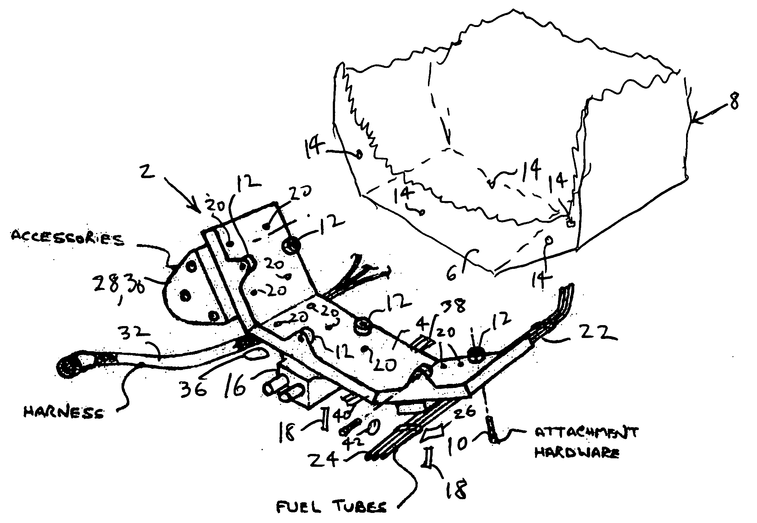
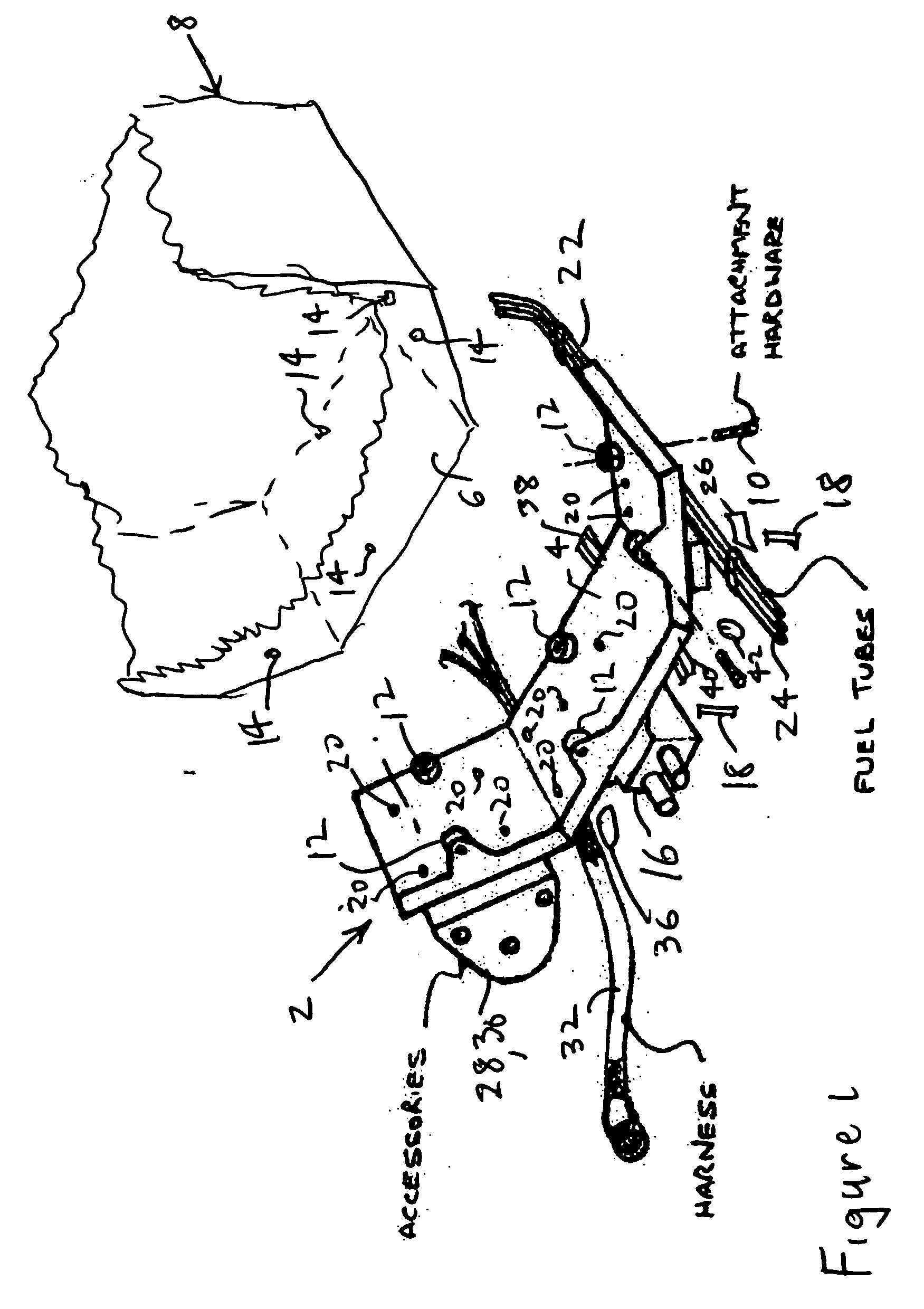
[0008]FIG. 1 is a perspective view of an APU multiple accessory support bracket or “super bracket”2 according to one possible embodiment of the invention. The super bracket 2 preferably has a mounting surface 4 with a shape and contour that lets the super bracket 2 form-fit snugly to a mating surface 6 of an APU 8 to which it attaches. The super bracket 2 preferably attaches to the APU mating surface 6 by way of primary fasteners 10 that pass through primary bracket attachment points 12 on the super bracket 2 and fasten to APU attachment points 14 on the APU mating surface 6. The fasteners 10 preferably comprise attachment bolts and the APU attachment points 14 preferably comprise mating threaded holes for the primary fasteners 10, although other attachment methods could be used. The primary bracket attachment points 12 preferably comprise vibration isolators that conveniently provide vibration isolation for all components mounted to the super bracket 2.

[0009] The super bracket 2 p...


PUM


Abstract

A multiple accessory support bracket that mounts a plurality of external accessories for an auxiliary power unit (APU) so that all the external accessories may be mounted to the APU in a single operation.

Description

FIELD OF THE INVENTION [0001] The invention relates to the assembly of a gas turbine engine such as an auxiliary power unit (APU), and more particularly a modularised system of assembling accessories onto an APU. BACKGROUND OF THE INVENTION [0002] Current APU designs for both commercial and military aeronautical applications have individually mounted external accessory components, such as line replaceable units (LRUs), tubes and electrical harnesses, as well as associated mounting brackets, clamps, isolators and bolts. The assembly of so many components onto the surfaces of the APU is a complex and time-consuming process. The number of assembly steps increases the likelihood of quality problems. Furthermore, the procurement and stocking of such a multitude of individual parts increases stored inventory and therefore increases the cost of the manufactured APU. SUMMARY OF THE INVENTION [0003] The invention comprises a special multiple accessory support bracket that serves to support a...

Claims


Application Information

Patent Timeline
IPC IPC(8): F21V21/00
CPCF05D2230/60F02C7/32
Inventor SUTTIE, PETER J.JEWESS, GORDON F.TA, KHANG D.OLDERBAK, MICHAEL J.DIOT, THOMAS H.MCQUILLAN, EDWARD R.GREGORY, DANIEL M.WORTHINGTON, STEPHENMAYBORNE, RUSTY E.KOHLS, MICHAEL D.HUGHES, DANIEL L.
Owner HAMILTON SUNDSTRAND CORP
Learn More