Supercharge Your Innovation With Domain-Expert AI Agents!

Laser projection module, depth camera and electronic device

A technology of laser projection and depth camera, applied in the field of imaging, can solve the problems of being unable to be completely diffracted and endangering the user's eyes, and achieve the effect of improving safety

Active Publication Date: 2018-09-04
GUANGDONG OPPO MOBILE TELECOMM CORP LTD
View PDF5 Cites 5 Cited by
  • Summary
  • Abstract
  • Description
  • Claims
  • Application Information

AI Technical Summary

Problems solved by technology

When the intensity of the zero-order beam is too strong, the zero-order beam cannot be completely diffracted when it is transmitted to the diffractive optical element, resulting in the intensity of the zero-order beam emitted by the diffractive optical element being too strong, which may endanger the user's eyes

Method used


Image

  • Laser projection module, depth camera and electronic device
  • Laser projection module, depth camera and electronic device
  • Laser projection module, depth camera and electronic device

Examples


Embodiment Construction

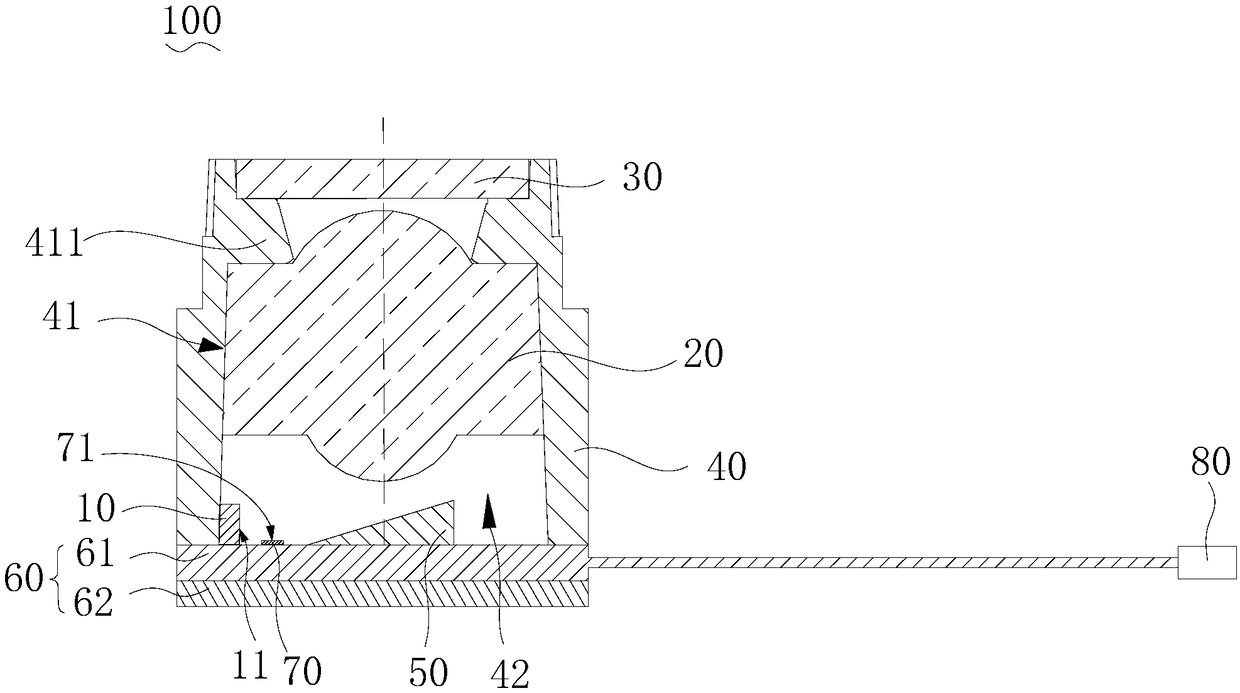
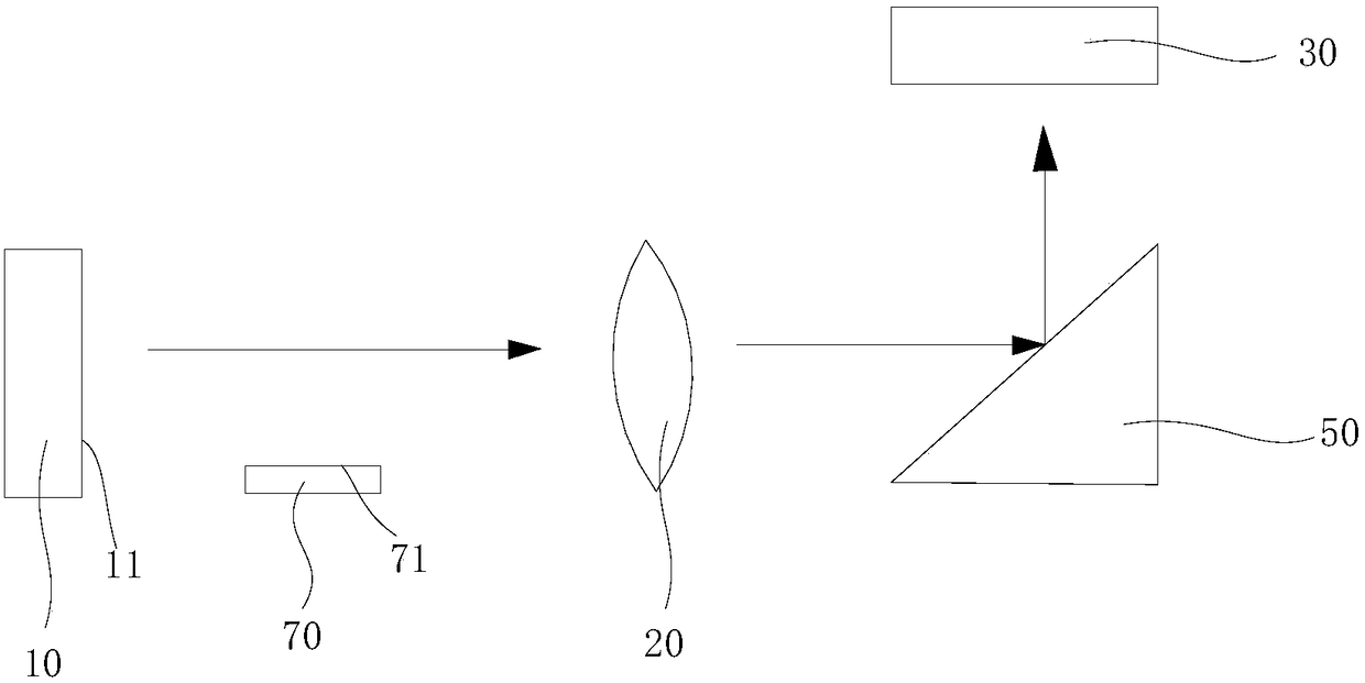
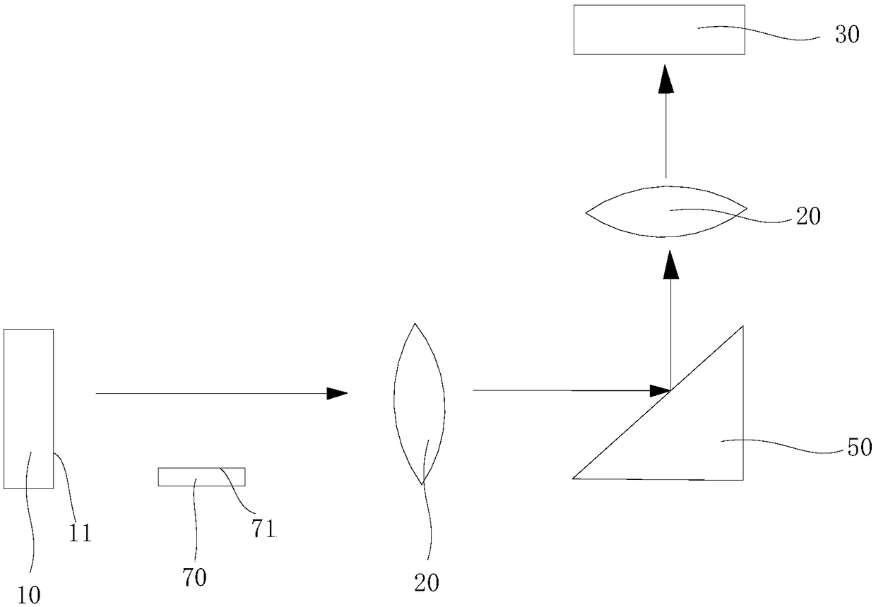
[0015] Embodiments of the present invention are described in detail below, examples of which are shown in the drawings, wherein the same or similar reference numerals designate the same or similar elements or elements having the same or similar functions throughout. The embodiments described below by referring to the figures are exemplary and are intended to explain the present invention and should not be construed as limiting the present invention.

[0016] In the description of the present invention, it should be understood that the terms "first" and "second" are used for description purposes only, and cannot be interpreted as indicating or implying relative importance or implicitly indicating the quantity of indicated technical features. Thus, a feature defined as "first" or "second" may explicitly or implicitly include one or more of said features. In the description of the present invention, "plurality" means two or more, unless otherwise specifically defined.

[0017] I...


PUM


Abstract

The present invention discloses a laser projection module. The laser projection module comprises a laser emitter, a reflection element, a diffraction optical element and an optical detector. The optical detector is arranged between the laser emitter and the reflection element, the optical detector is configured to receive the laser to output electrical signals, and the electrical signals are configured to determine the non-zero level beam intensity of the laser and reduce the emission power of the laser emitter when the non-zero level beam intensity is smaller than a preset intensity. The present invention further discloses a depth camera and an electronic device. The optical detector is arranged between the laser emitter and the reflection element, when the optical detector is employed todetect that the non-zero level beam intensity is small, the energy of a zero-level beam can be too large, at the same time, motion of reducing the emission power of the laser emitter is immediately executed to avoid the problem that the too large zero-level beam energy damages the user's eyes and improve the usage safety of the laser projection module.

Description

technical field [0001] The invention relates to the field of imaging technology, in particular to a laser projection module, a depth camera and an electronic device. Background technique [0002] When a laser transmitter emits laser light, the laser light will diverge. After the laser diverges, the light beams superimposed and gathered at the center of the light-emitting surface of the laser emitter are zero-order light beams, and the light beams transmitted around the light-emitting surface of the laser emitter are non-zero-order light beams. When the intensity of the zero-order beam is too strong, the zero-order beam cannot be completely diffracted when transmitted to the diffractive optical element, resulting in the intensity of the zero-order beam emitted by the diffractive optical element being too strong, which may endanger users' eyes. Contents of the invention [0003] Embodiments of the present invention provide a laser projection module, a depth camera and an el...

Claims


Application Information

Patent Timeline
IPC IPC(8): G02B27/42G01S17/89
CPCG02B27/4205G01S17/89G01B11/25G01S7/4814G01S7/497H01S5/02469H01S5/0683H04M1/0272G02B27/425H04M1/0264H04N5/2226H01S5/0236H01S5/02255H01S5/02253H04N23/56H04N13/254H04N13/296G02B27/30H04N23/51
Inventor 周奇群
Owner GUANGDONG OPPO MOBILE TELECOMM CORP LTD
Features
  • R&D
  • Intellectual Property
  • Life Sciences
  • Materials
  • Tech Scout
  • Unparalleled Data Quality
  • Higher Quality Content
  • 60% Fewer Hallucinations
Learn More