Solar energy escape indicating device for building and use method thereof
A technology of indicating device and solar energy, applied in display devices, signal devices, instruments, etc., can solve the problems of inflexibility, changing the escape direction, and inability to adjust in real time, and achieve the effect of good use effect, energy saving, and increase of installation quantity.
- Summary
- Abstract
- Description
- Claims
- Application Information
AI Technical Summary
Problems solved by technology
Method used
Image

Examples
Embodiment 1
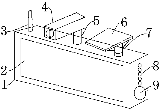
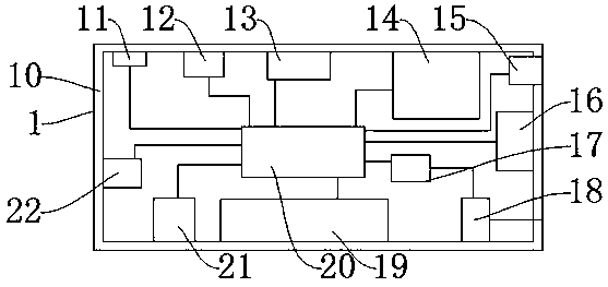
[0026] Such as Figure 1-Figure 5 As shown, a solar energy escape indicating device for buildings includes a rubber shell 1, a sign 2, a camera 4, a rotating shaft 7, and a sealing and shock-absorbing layer 10. The outer surface of the rubber shell 1 is provided with the sign 2 , the signboard 2 indicates the escape route, the top of the rubber housing 1 is provided with a signal transmitting antenna 3, and the signal transmitting antenna 3 transmits wireless signals, and one side of the signal transmitting antenna 3 is provided with the Camera 4, the camera 4 monitors the internal conditions of the building, a support frame 5 is arranged on one side of the camera 4, and the support frame 5 fixes and supports the camera 4, and a solar energy is installed on one side of the support frame 5 plate 6, the solar panel 6 absorbs solar energy and converts solar energy into electrical energy, the rotating shaft 7 is installed on the lower side of the solar panel 6, and an alarm indica...
Embodiment 2
[0028] The difference between this embodiment and Embodiment 1 is:
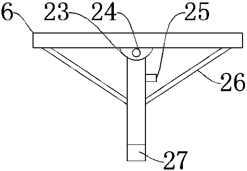
[0029]The sign 2 is nested inside the rubber shell 1, the sign 2 is composed of LED lights, the solar tracking sensor 25 is fixed above the rotating shaft 7 by bolts, and the shaft end sheath 27 is nested and connected with the rotating shaft 7, and each of the powerful magnets 28 and the double-sided adhesive layer 29 has four pieces, and the four strong magnets 28 and the double-sided adhesive layer 29 are all arranged on the rubber shell Body 1 has four corners on the back.
[0030] Specifically, such setting can save a lot of power, and at the same time, it can facilitate the installation of the device, effectively increase the number of devices installed, and facilitate the monitoring of the interior of the building.
[0031] The present invention also provides a method for using a solar energy escape indicator device for buildings, which is applied to the above solar energy escape indicator device for ...
PUM
 Abstract
Description
Claims
Application Information
 - R&D
- Intellectual Property
- Life Sciences
- Materials
- Tech Scout
- Unparalleled Data Quality
- Higher Quality Content
- 60% Fewer Hallucinations
Browse by: Latest US Patents, China's latest patents, Technical Efficacy Thesaurus, Application Domain, Technology Topic, Popular Technical Reports.
© 2025 PatSnap. All rights reserved.Legal|Privacy policy|Modern Slavery Act Transparency Statement|Sitemap|About US| Contact US: help@patsnap.com