
Over-voltage and under-voltage protection circuit with hysteresis

A protection circuit, overvoltage and undervoltage technology, applied in emergency protection circuit devices, protection against overvoltage, emergency protection devices with automatic disconnection, etc., can solve the problem of reducing circuit reliability, reducing device service life, increasing The probability of device damage and other problems can be improved to improve reliability, reduce the number of repeated switching on and off, and improve the service life.

Active Publication Date: 2018-09-04
LUOYANG LONGSHENG SCI & TECH
View PDF4 Cites 0 Cited by
  • Summary
  • Abstract
  • Description
  • Claims
  • Application Information

AI Technical Summary

Problems solved by technology

In the actual circuit, the input voltage often changes back and forth around the lowest value or the highest value of the input voltage range of the circuit, which will cause the back-end circuit to be turned on and off repeatedly, which increases the damage probability of the device, reduces the service life of the device, and reduces the circuit reliability

Method used


Image

  • Over-voltage and under-voltage protection circuit with hysteresis
  • Over-voltage and under-voltage protection circuit with hysteresis
  • Over-voltage and under-voltage protection circuit with hysteresis

Examples


Embodiment 1

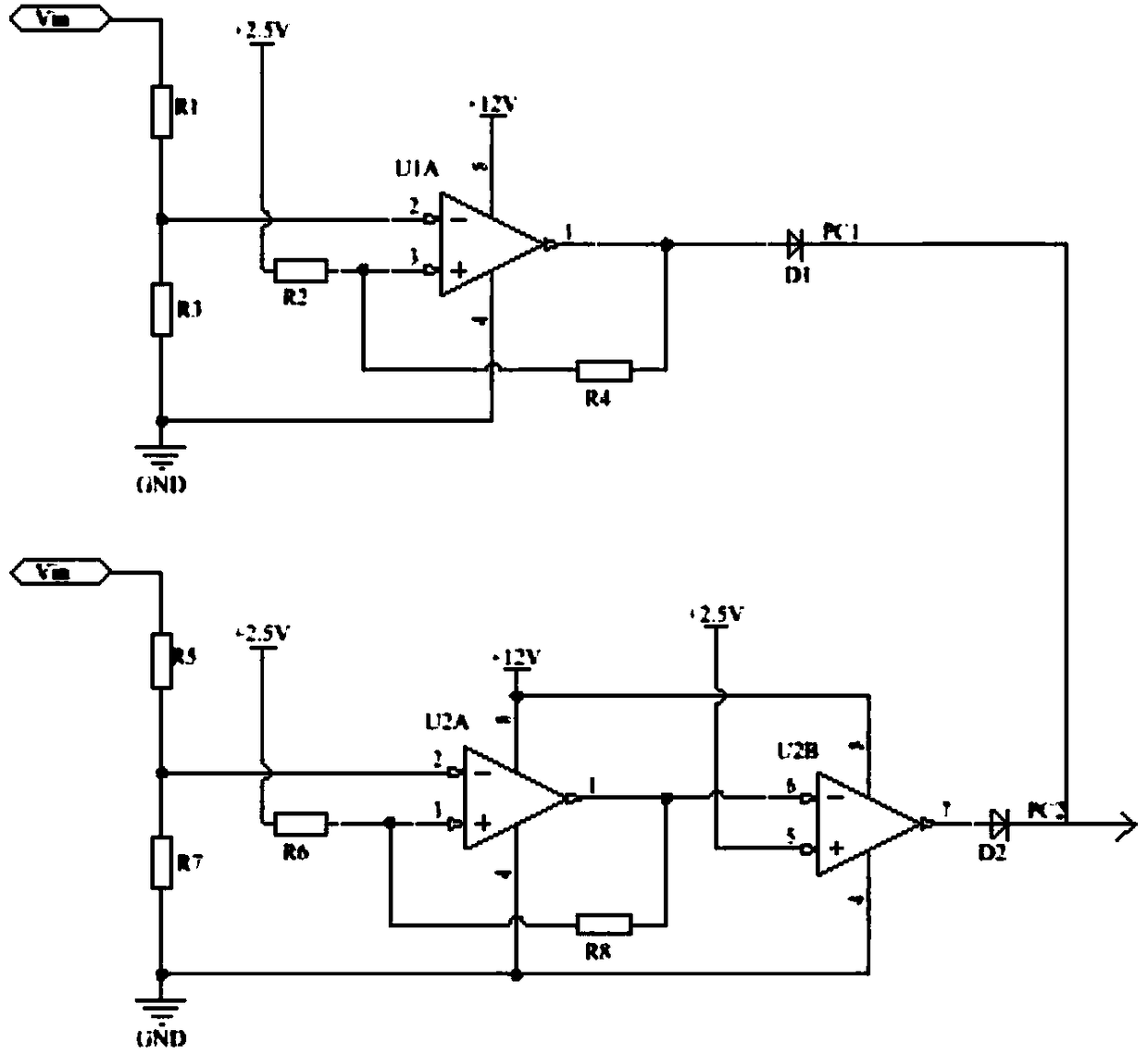
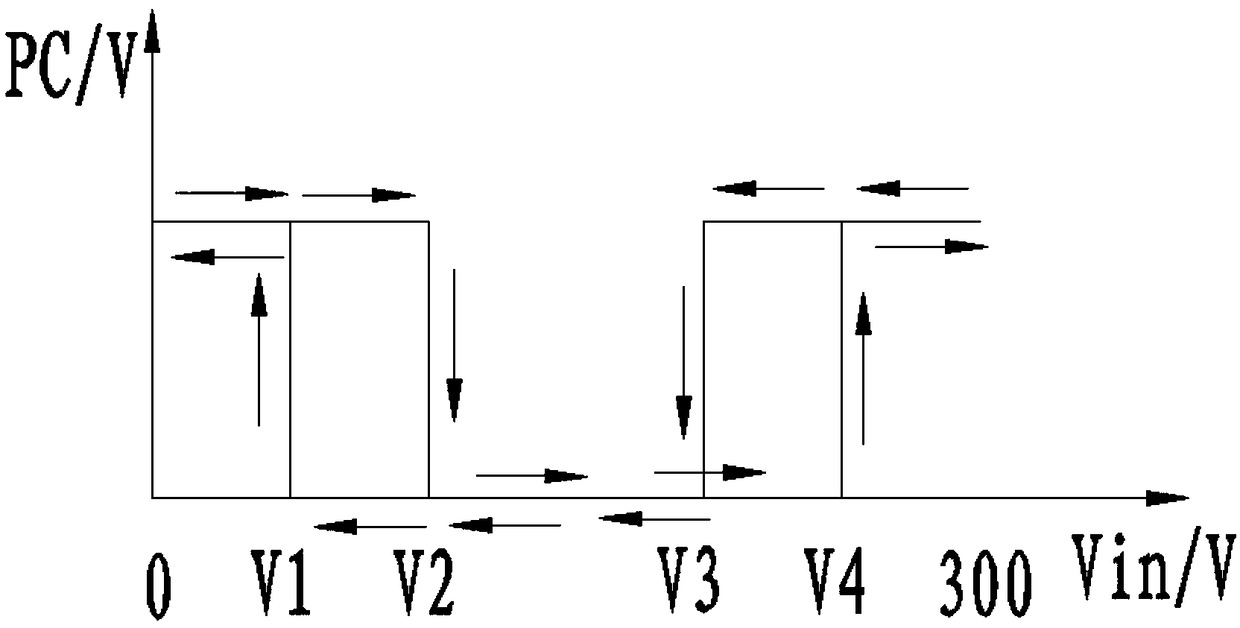
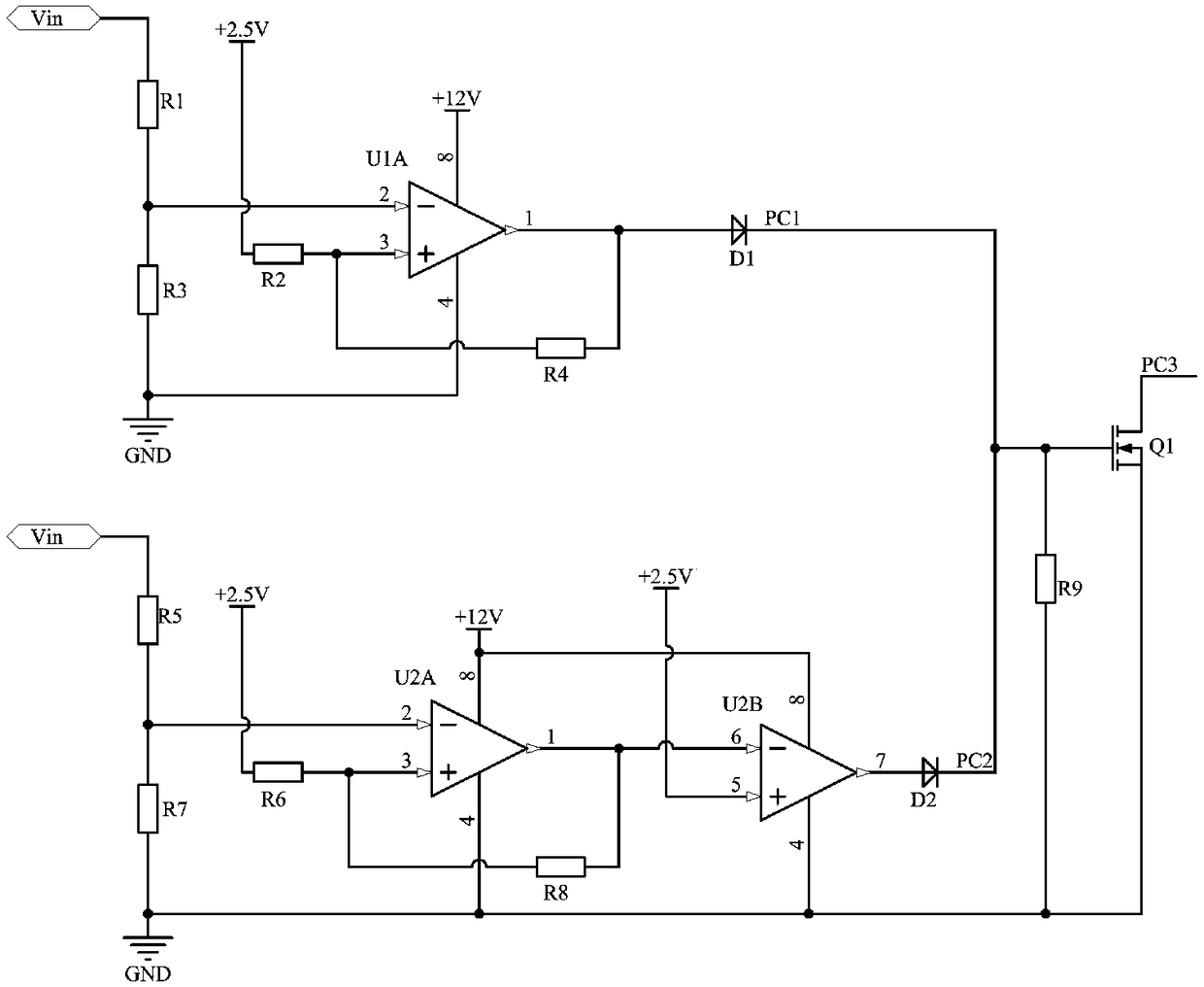
[0025] image 3 Among them, resistor R9, MOS transistor Q1, logic output control signal PC3, and other devices are the same figure 1 . The circuit realizes that when the input voltage Vin is normal, PC3 is in a high level (high impedance) state; when the circuit has overvoltage and undervoltage protection, PC3 is in a low level (grounding) state.

[0026] When the input DC power supply Vin changes from 0V to the undervoltage recovery point (V2), the logic output control signal PC1 is connected to the logic output control signal PC2 and becomes high level, and PC3 is in a low level (grounded) state, and the back-end circuit is protected ;

[0027] When the input DC power supply Vin changes from the undervoltage recovery point (V2) to the overvoltage protection point (V4), the logic output control signal PC1 is connected to the logic output control signal PC2 and is low level, and PC3 is high level (high impedance) state, the back-end circuit works normally;

[0028] When th...

Embodiment 2

[0033] Figure 4 Among them, resistors R10, R11, anti-logic optocoupler U3, logic output control signal PC4, logic output control signal ground PC4-GND, and other devices are the same figure 1 . The circuit realizes that when the input voltage Vin is normal, PC4 is in a low level (grounding) state; when the circuit has overvoltage and undervoltage protection, PC4 is in a high level (high impedance) state. There is also the role of front and rear end isolation.

[0034] When the input DC power supply Vin changes from 0V to the undervoltage recovery point (V2), the logic output control signal PC1 is connected to the logic output control signal PC2 and is at a high level, and PC4 is at a high level (high impedance) state, and the back-end circuit occurs Protect;

[0035] When the input DC power supply Vin changes from the undervoltage recovery point (V2) to the overvoltage protection point (V4), the logic output control signal PC1 is connected to the logic output control signal ...


PUM


Abstract

The invention relates to the technical field of power sources, and discloses an over-voltage and under-voltage protection circuit with hysteresis. The over-voltage and under-voltage protection circuitincludes an input DC input power source, an auxiliary input power source and a logic output control signal; a single under-voltage point is discomposed into an under-voltage protection point (V1) anda under-voltage recovery point (V2), and the voltages of the under-voltage protection point (V1) and the under-voltage recovery point (V2) can be set by resistors R1 to R4, so that a back-end circuitis not repeatedly turned on and off on in the vicinity of the under-voltage point. A single over-voltage is decomposed into an over-voltage recovery point (V3) and an over-voltage protection point (V4), and the voltages of the over-voltage recovery point (V3) and the over-voltage protection point (V4) can be set by resistors R5 to R8, so that the back-end circuit is not repeatedly turned on and off in the vicinity of the over-voltage point. The invention reduces the number of times the device is repeatedly turned on and off, reduces the probability of device damage, improves the reliability of the back-end circuit, indirectly prolongs the service life of the device, and reduces the product use cost.

Description

technical field [0001] The invention relates to the technical field of a power supply, in particular to an overvoltage and undervoltage protection circuit with hysteresis. Background technique [0002] Under normal circumstances, the overvoltage and undervoltage protection circuit of the power supply uses a window voltage comparator. When the input voltage is lower than the lowest value of the circuit input voltage range or higher than the highest value of the circuit input voltage range, the back-end circuit is turned off to protect the back-end circuit. function. In the actual circuit, the input voltage often changes back and forth around the lowest value or the highest value of the input voltage range of the circuit, which will cause the back-end circuit to be turned on and off repeatedly, which increases the damage probability of the device, reduces the service life of the device, and reduces the circuit reliability. [0003] Therefore, this new circuit is designed to ...

Claims


Application Information

Patent Timeline
Patent Type & Authority Applications(China)
IPC IPC(8): H02H3/24H02H3/20
CPCH02H3/207H02H3/243
Inventor 李跃闯
Owner LUOYANG LONGSHENG SCI & TECH
Learn More