
Motor permanent magnet magnetic pole transition structure for improving normal electromagnetic force

A transitional structure, permanent magnet technology, applied in the shape/pattern/structure of magnetic circuit, synchronous motor with stationary armature and rotating magnet, magnetic circuit, etc. It can improve the normal electromagnetic force and normal electromagnetic force, and reduce vibration and noise.

Inactive Publication Date: 2018-09-04
SHANGHAI UNIV OF ENG SCI
View PDF5 Cites 4 Cited by
  • Summary
  • Abstract
  • Description
  • Claims
  • Application Information

AI Technical Summary

Problems solved by technology

The shape of the permanent magnet of the common surface-mounted permanent magnet synchronous motor is mainly divided into two types. One is cylindrical, which is directly placed on the outer surface of the rotor. The manufacturing process is simple and the installation is convenient, but the amount of permanent magnets is too large. The cost is too high, and the solid is gradually eliminated; the other is the current common tile-shaped permanent magnet, and multiple tile-shaped permanent magnets are discontinuously attached to the outer surface of the rotor. Compared with the cylindrical permanent magnet, this type of permanent magnet The dosage is greatly reduced
However, in the discontinuous permanent magnet magnetic pole transition structure, the magnetic field has a large jump, resulting in a large air-gap flux density harmonic content and a high sinusoidal distortion rate, which in turn makes the normal electromagnetic force of the motor high in harmonic content and amplitude. Eventually, it will cause a large vibration and noise problem, which will have a serious impact on the performance of the motor

Method used


Image

  • Motor permanent magnet magnetic pole transition structure for improving normal electromagnetic force
  • Motor permanent magnet magnetic pole transition structure for improving normal electromagnetic force
  • Motor permanent magnet magnetic pole transition structure for improving normal electromagnetic force

Examples


Embodiment

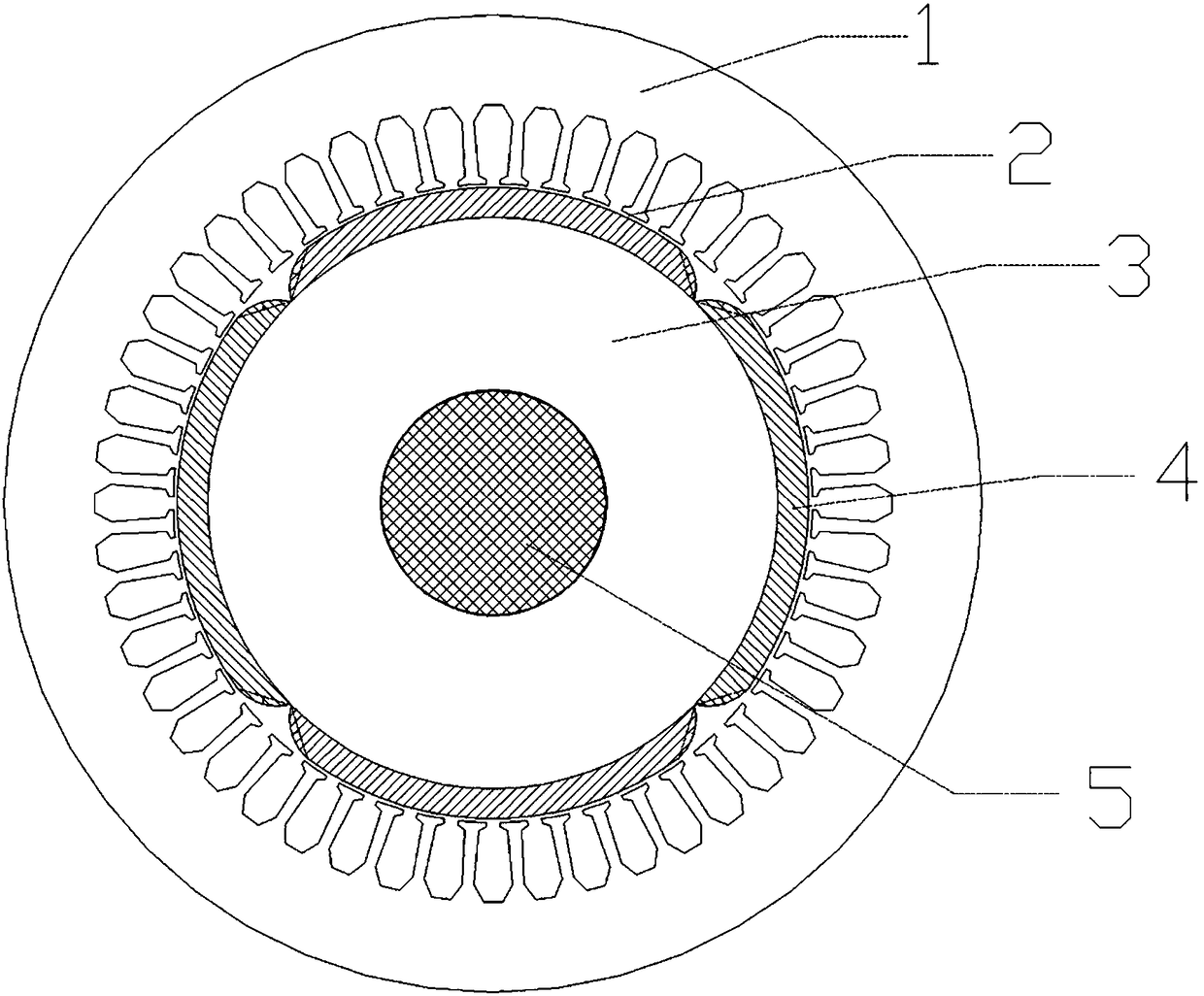
[0028] Aiming at the problems caused by the current surface-mounted permanent magnet synchronous motor with discontinuous permanent magnet transition, the invention proposes a new permanent magnet magnetic pole transition structure.

[0029] Including stator core, air gap, rotor core, permanent magnet poles, and rotating shaft.

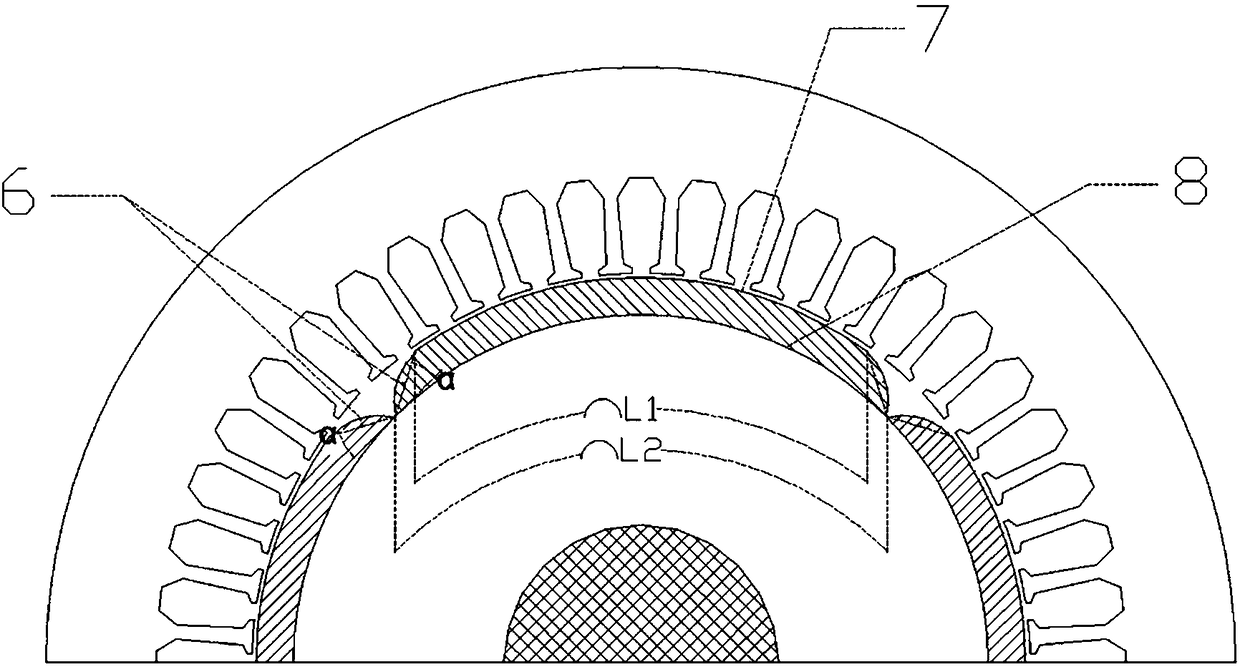
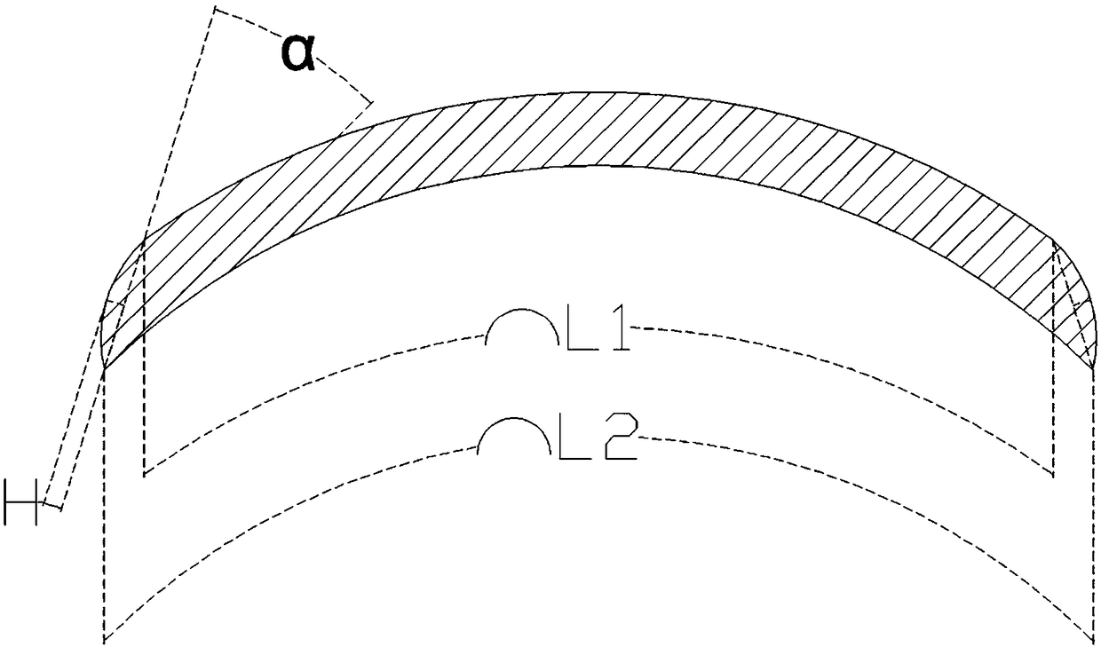
[0030] The magnetic poles of two adjacent permanent magnets of the surface-mounted permanent magnet synchronous motor intersect at the inner end of the permanent magnet magnetic pole, and the magnetic poles of the two adjacent permanent magnets only coincide at this point; the outer arc length of the permanent magnet magnetic pole of the surface-mounted permanent magnet synchronous motor is L 1 Calculate the length of the motor circuit, the inner arc length L 2 =2πR / P, and satisfy the relation L 1 2 .

[0031] Surface-mounted permanent magnet synchronous motor The angle between the chord of the magnetic pole hypotenuse of the surface-mounted permane...


PUM


Abstract

The invention relates to a motor permanent magnet magnetic pole transition structure for improving normal electromagnetic force. The motor permanent magnet magnetic pole transition structure for improving normal electromagnetic force includes a rotating shaft, a rotor core, permanent magnet poles and the stator core in sequence from the inside to the outside; air gaps are formed between the permanent magnet poles and the stator core; a plurality of permanent magnet poles are provided, and are evenly distributed in the circumferential direction; the inner surfaces of the adjacent permanent magnet poles only contact at the end points while the outer surfaces are not touched, and both the inner and outer surfaces are arc-shaped; the bevel edges between the inner and outer surfaces are arc-shaped. Compared with the prior art, the motor permanent magnet magnetic pole transition structure for improving normal electromagnetic force has the advantages that the air gap magnetic density waveformis close to sine; the amplitude of the normal electromagnetic force reduces; and finally vibration and noise of the motor can be reduced.

Description

technical field [0001] The invention relates to the technical field of motors, in particular to a permanent magnet magnetic pole transition structure of a surface-mounted permanent magnet synchronous motor which improves the normal electromagnetic force. Background technique [0002] In recent decades, with the advent of alnico permanent magnets, ferrite permanent magnets, and especially rare earth permanent magnets, the magnetic performance has been greatly improved, and many electric excitation motors have switched to permanent magnet excitation. Compared with electric excitation motors, permanent magnet motors have significant advantages such as simple structure, reliable operation, small size, light weight, low loss, high efficiency, and flexible and diverse shapes and sizes of motors. It can not only replace some traditional electric excitation Motors, and can achieve high performance that is difficult to achieve with electric excitation motors. At present, permanent m...

Claims


Application Information

Patent Timeline
Patent Type & Authority Applications(China)
IPC IPC(8): H02K21/14H02K21/02H02K1/27
CPCH02K21/14H02K1/278H02K21/026H02K2201/03H02K2213/03
Inventor 王长城郭辉王岩松孙裴刘宁宁
Owner SHANGHAI UNIV OF ENG SCI
Learn More