Cutting device used for hardware plate
A technology for cutting devices and plates, applied in the direction of shearing devices, shearing machine accessories, metal processing equipment, etc., can solve problems such as time-consuming, labor-intensive, life-threatening and dangerous
- Summary
- Abstract
- Description
- Claims
- Application Information
AI Technical Summary
Problems solved by technology
Method used
Image

Examples
Embodiment 1
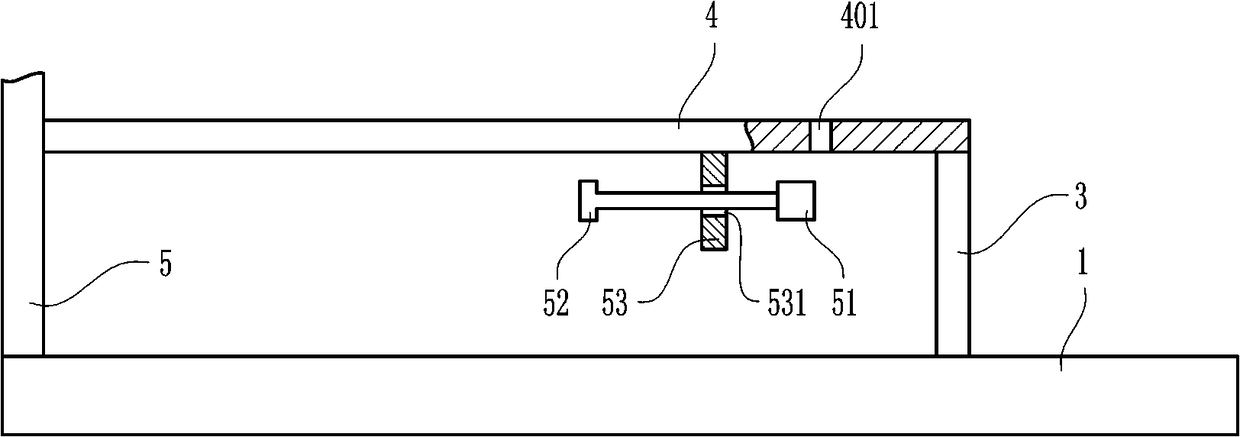
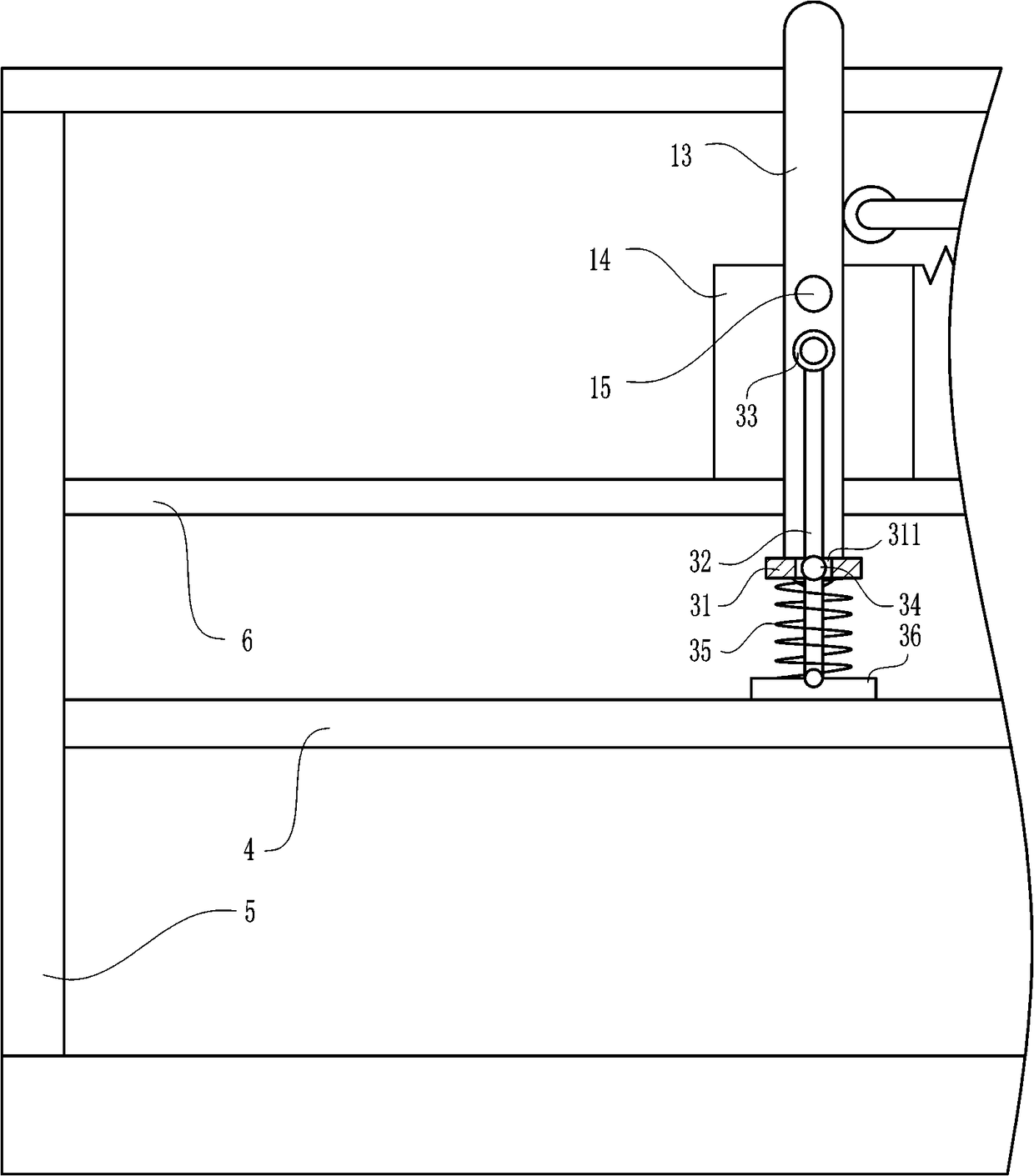
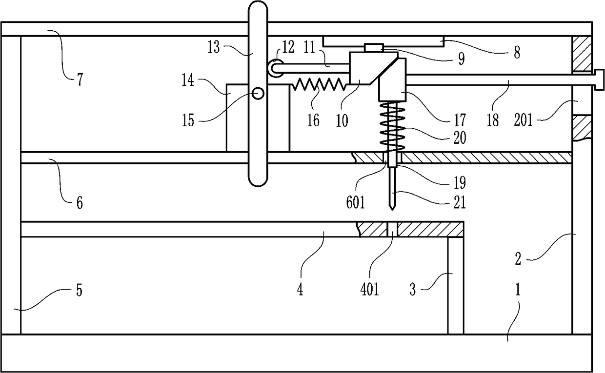
[0027] A cutting device for metal sheets, such as Figure 1-5 As shown, it includes a base 1, a first bracket 2, a small bracket 3, a workbench 4, a second bracket 5, a long connecting rod 6, a top plate 7, a slide rail 8, a slider 9, a first wedge block 10, a small connection Rod 11, contact wheel 12, swing lever 13, large fixed plate 14, rotating shaft 15, extension spring 16, second wedge block 17, long guide rod 18, lifting rod 19, first spring 20 and cutter 21, the first The support 2 is located above the base 1, the first support 2 is connected to the base 1, the small support 3 is located on the left side of the first support 2, the bottom of the small support 3 is connected to the top of the base 1, and the workbench 4 is located above the small support 3. Workbench 4 is connected with small support 3, and second support 5 is positioned at the left side of workbench 4, and second support 5 is connected with workbench 4, and the bottom of second support 5 is connected w...
Embodiment 2
[0029] A cutting device for metal sheets, such as Figure 1-5 As shown, it includes a base 1, a first bracket 2, a small bracket 3, a workbench 4, a second bracket 5, a long connecting rod 6, a top plate 7, a slide rail 8, a slider 9, a first wedge block 10, a small connection Rod 11, contact wheel 12, swing lever 13, large fixed plate 14, rotating shaft 15, extension spring 16, second wedge block 17, long guide rod 18, lifting rod 19, first spring 20 and cutter 21, the first The support 2 is located above the base 1, the first support 2 is connected to the base 1, the small support 3 is located on the left side of the first support 2, the bottom of the small support 3 is connected to the top of the base 1, and the workbench 4 is located above the small support 3. Workbench 4 is connected with small support 3, and second support 5 is positioned at the left side of workbench 4, and second support 5 is connected with workbench 4, and the bottom of second support 5 is connected w...
Embodiment 3
[0032] A cutting device for metal sheets, such as Figure 1-5 As shown, it includes a base 1, a first bracket 2, a small bracket 3, a workbench 4, a second bracket 5, a long connecting rod 6, a top plate 7, a slide rail 8, a slider 9, a first wedge block 10, a small connection Rod 11, contact wheel 12, swing lever 13, large fixed plate 14, rotating shaft 15, extension spring 16, second wedge block 17, long guide rod 18, lifting rod 19, first spring 20 and cutter 21, the first The support 2 is located above the base 1, the first support 2 is connected to the base 1, the small support 3 is located on the left side of the first support 2, the bottom of the small support 3 is connected to the top of the base 1, and the workbench 4 is located above the small support 3. Workbench 4 is connected with small support 3, and second support 5 is positioned at the left side of workbench 4, and second support 5 is connected with workbench 4, and the bottom of second support 5 is connected w...
PUM
 Abstract
Description
Claims
Application Information
 - R&D
- Intellectual Property
- Life Sciences
- Materials
- Tech Scout
- Unparalleled Data Quality
- Higher Quality Content
- 60% Fewer Hallucinations
Browse by: Latest US Patents, China's latest patents, Technical Efficacy Thesaurus, Application Domain, Technology Topic, Popular Technical Reports.
© 2025 PatSnap. All rights reserved.Legal|Privacy policy|Modern Slavery Act Transparency Statement|Sitemap|About US| Contact US: help@patsnap.com