
Clamping device for industrial automation

An industrial automation and clamping device technology, applied in the field of automation, can solve the problems of longitudinal slip, unlimited longitudinal direction, etc., and achieve the effect of preventing the reduction of service life, facilitating hoisting operations, and facilitating installation

Inactive Publication Date: 2018-09-07
芜湖市涵润智能科技有限公司
View PDF5 Cites 24 Cited by
  • Summary
  • Abstract
  • Description
  • Claims
  • Application Information

AI Technical Summary

Problems solved by technology

[0005] Aiming at the deficiencies of the prior art, the present invention provides a clamping device for industrial automation, which solves the problem that the clamping devices of existing industrial automation processing equipment generally only adopt the horizontal clamping mode and the longitudinal direction is not limited, resulting in the horizontal direction of the workpiece. There will be a problem of slippage in the longitudinal direction when the clamp is loose

Method used


Image

  • Clamping device for industrial automation
  • Clamping device for industrial automation

Examples


Embodiment Construction

[0021] The following will clearly and completely describe the technical solutions in the embodiments of the present invention with reference to the accompanying drawings in the embodiments of the present invention. Obviously, the described embodiments are only some, not all, embodiments of the present invention. Based on the embodiments of the present invention, all other embodiments obtained by persons of ordinary skill in the art without making creative efforts belong to the protection scope of the present invention.

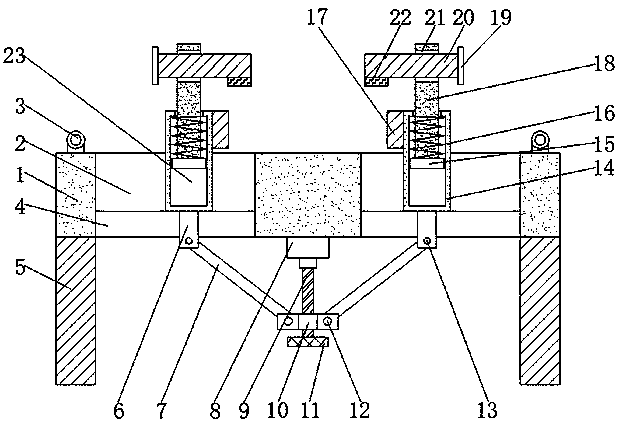
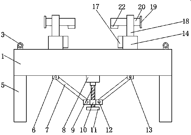
[0022] see Figure 1-2 , the present invention provides a technical solution: a clamping device for industrial automation, including a fixed block 1, the bottom surface of the fixed block 1 is fixedly connected with two symmetrical mounting columns 5, and the two mounting columns 5 are respectively located on two The two sides of the support rod 7 can make the device easy to install, so that the user can use it. The upper surface of the fixed block 1 is provid...


PUM


Abstract

The invention discloses a clamping device for industrial automation. The clamping device comprises a fixing block, the upper surface of the fixing block is provided with two symmetrical sliding grooves, sliding blocks matched with the sliding grooves are arranged in the sliding grooves in a clamped connection mode correspondingly, each sliding block is internally provided with a cavity, first movable rods are placed inside the cavities correspondingly, the top ends of the two first movable rods penetrate through the two cavities and extend to the positions above the sliding blocks, and movableplates matched with the sliding blocks are placed inside the sliding blocks correspondingly. According to the clamping device for industrial automation, since a forward-reverse rotation motor is arranged, the two sliding blocks are made to be close to each other under the effect of push rods, a screw rod and a screw ring, and workpieces can be clamped in the horizontal direction conveniently; since sliding rods are arranged, under the effect of springs, the first movable rods and through holes, the first movable rods can ascend and descend, the sliding rods can move left and right, accordingly, the workpieces are fastened in the vertical direction conveniently, and the purpose that the machined workpieces are longitudinally clamped is achieved.

Description

technical field [0001] The invention relates to the technical field of automation, in particular to a clamping device for industrial automation. Background technique [0002] Automation refers to the process of realizing the expected goal through automatic detection, information processing, analysis and judgment, manipulation and control according to human requirements without the direct participation of people or fewer people. Automation technology is widely used In industry, agriculture, military, scientific research, transportation, commerce, medical care, service and family, etc. [0003] The existing automation technology is widely used in industrial processing. It can be applied from blank manufacturing to processing, assembly to final inspection and packaging. The existing automation technology generally adopts horizontal clamping methods in industrial processing. Clamping, and the vertical direction of the workpiece is generally unlimited, which makes the workpiece ...

Claims


Application Information

Patent Timeline
Patent Type & Authority Applications(China)
IPC IPC(8): B23Q3/06
CPCB23Q3/06
Inventor 蔡敬东
Owner 芜湖市涵润智能科技有限公司
Learn More