
A flexible manipulator based on ball joint

A flexible manipulator and ball joint technology, applied in the field of intelligent manipulators, can solve the problems of heavy rigid joints, poor flexible bending effect, and small bending curvature, etc., and achieve the effect of compact structure, high degree of freedom, and high compliance

Active Publication Date: 2020-09-01
SHENZHEN GRADUATE SCHOOL TSINGHUA UNIV
View PDF6 Cites 0 Cited by
  • Summary
  • Abstract
  • Description
  • Claims
  • Application Information

AI Technical Summary

Problems solved by technology

The joints of the flexible robotic arm in the related art adopt a cross universal structure, and the bending angle of the whole arm is obtained by using the bending degree of freedom of the rigid joint. The mass of the rigid joint is relatively heavy, so the whole arm itself is too heavy, and a large driving power is required. At the same time, the bending curvature obtained by using the degree of freedom of the rigid joint around the axis is small, and the flexible bending effect of the whole arm is poor; there are also some flexible manipulators made of pure flexible materials, which improve the flexible bending effect of the whole arm, but there is an axial compression problem

Method used


Image

  • A flexible manipulator based on ball joint
  • A flexible manipulator based on ball joint
  • A flexible manipulator based on ball joint

Examples


Embodiment Construction

[0022] The present invention will be further described below with reference to the accompanying drawings and in combination with preferred embodiments.

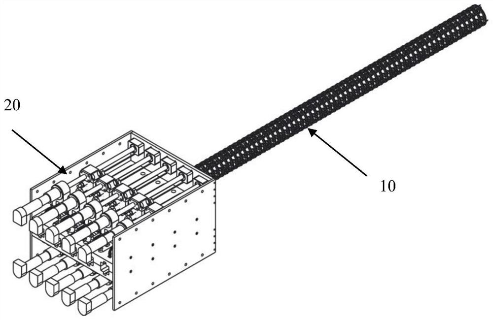
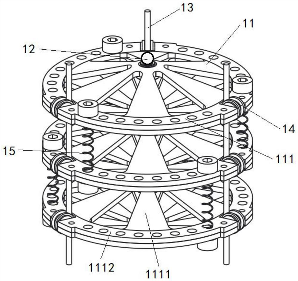
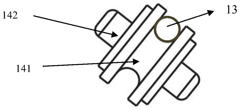
[0023] Such as figure 1 As shown, the preferred embodiment of the present invention discloses a flexible mechanical arm based on a ball joint, including an arm segment mechanism 10 and a drive mechanism 20, and the arm segment mechanism 10 includes multiple joint segments connected to each other in sequence, wherein the structure of the joint segments is as follows figure 2 As shown, each joint segment includes multiple joint modules 11 , multiple ball joints 12 , multiple ropes 13 , multiple guide rope modules 14 and multiple elastic connection modules 15 .

[0024] The joint module 11 includes two interconnected joint units 111, each joint unit 111 includes a conical protrusion 1111 and a flange 1112, the flange 1112 is connected to the circular extension of the bottom of the conical protrusion 1111, the two The flanges 1...


PUM


Abstract

The invention discloses a flexible mechanical arm based on ball hinging. The flexible mechanical arm based on ball hinging comprises a driving mechanism and an arm segment mechanism. The arm segment mechanism comprises at least one joint segment. The joint segments are connected together in sequence. Each joint segment comprises a plurality of joint modules, a plurality of ball joints, a pluralityof ropes and a plurality of elastic connecting modules. Each joint module comprises a flange portion and two conical convex portions, the two conical convex portions are arranged on the two sides ofthe flange portion respectively, and the flange portion is connected to circular extension parts at the bottoms of the conical convex portions on the two sides. Every two adjacent joint modules are connected through a plurality of elastic connecting modules, and the top ends of the two adjacent conical convex portions of every two adjacent joint modules are hinged through a ball joint. First endsof the multiple ropes are connected with the driving mechanism respectively, the ropes are driven by the driving mechanism, and second ends of the ropes are fixedly connected to the joint module at the tail end after passing through multiple joint modules in sequence. With the flexible mechanical arm based on ball hinging, the problems about horizontal compression can be solved, and a flexible bending effect is very good.

Description

technical field [0001] The invention relates to the field of intelligent mechanical arms, in particular to a flexible mechanical arm based on ball joints. Background technique [0002] The traditional rigid articulated manipulator has a large and heavy structure, a large operating space, and poor flexibility, which greatly restricts its application in a narrow working space environment. Due to the advantages of large length-to-diameter ratio, many degrees of freedom, flexible movements, and strong environmental adaptability, flexible manipulators are easy to flexibly adjust poses, expand workspaces, avoid obstacles, and overcome singularities in narrow spaces. The joints of the flexible robotic arm in the related art adopt a cross universal structure, and the bending angle of the whole arm is obtained by using the bending degree of freedom of the rigid joint. The mass of the rigid joint is relatively heavy, so the whole arm itself is too heavy, and a large driving power is r...

Claims


Application Information

Patent Timeline
Patent Type & Authority Patents(China)
IPC IPC(8): B25J18/06B25J17/00B25J17/02
CPCB25J17/00B25J17/02B25J18/06
Inventor 梁斌王学谦王乐天于行尧孟得山
Owner SHENZHEN GRADUATE SCHOOL TSINGHUA UNIV
Learn More