Gasification device for sludge treatment

A gasification device and sludge treatment technology, which is applied in the direction of water/sludge/sewage treatment, pyrolysis treatment of sludge, water pollutants, etc., can solve the problem of low gasification temperature, low gasification amount, and heavy metals that cannot be glassed State curing and other issues, to achieve the effect of uniform air distribution

Pending Publication Date: 2018-09-07
湖南省益能环保科技有限公司
View PDF0 Cites 1 Cited by
  • Summary
  • Abstract
  • Description
  • Claims
  • Application Information

AI Technical Summary

Problems solved by technology

[0002] At present, the special gasification device for sludge is mainly used to treat sludge and gasify the biomass with high calorific value, but the existing sludge treatment gasification device mainly has the following technical problems: due to uneven air distribution, resulting in The combustion temperature does not meet the requirements of complete gasification, and the low gasification temperature only gasifies the essence of the biomass, and the fixed carbon in it is not gasified; and the heavy metals after gasification cannot be solidified in the glass state, which cannot be realized. full gasification
In addition, the gasification speed is slow and the amount of gasification is small

Method used


Image

  • Gasification device for sludge treatment
  • Gasification device for sludge treatment
  • Gasification device for sludge treatment

Examples


Embodiment Construction

[0020] Below, the present invention will be further described in conjunction with the accompanying drawings and specific implementation methods. It should be noted that, under the premise of not conflicting, the various embodiments described below or the technical features can be combined arbitrarily to form new embodiments. .

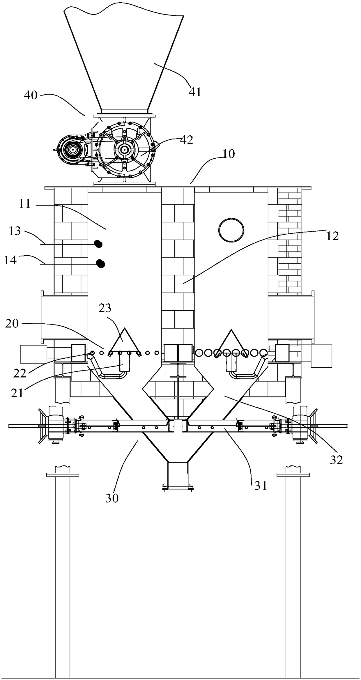
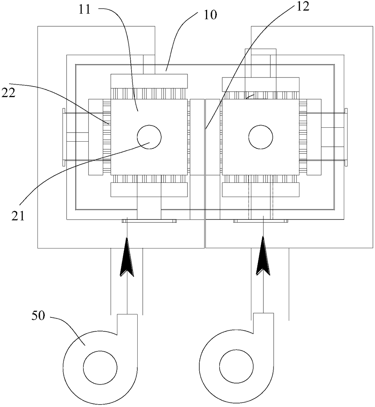
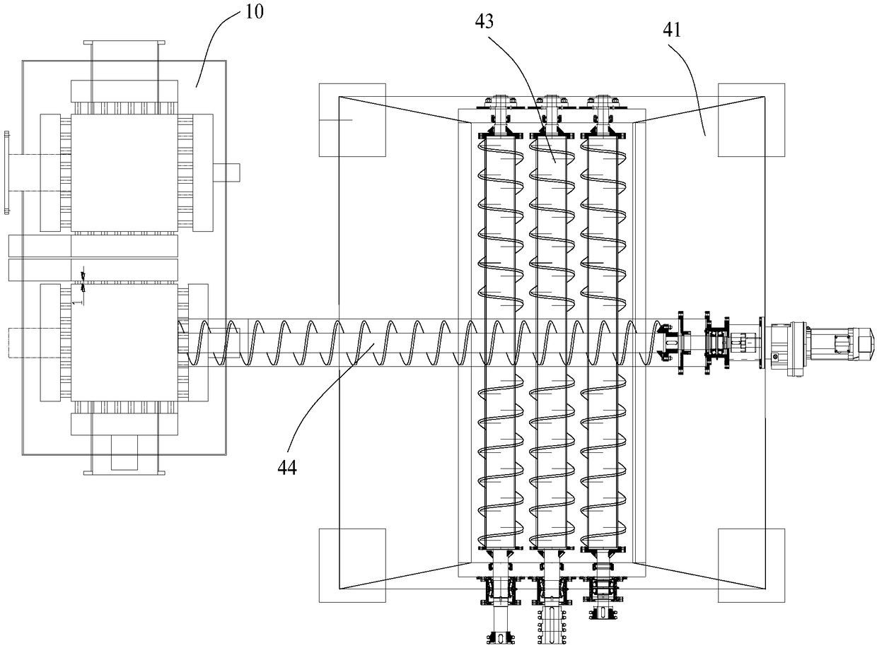
[0021] like figure 1 , figure 2 as well as image 3 The shown gasification device for sludge treatment includes a combustion chamber 10, an ignition device, a fan 50, an air duct assembly 20 and a slagging device 30; the specific air duct assembly 20 includes a first air duct 21 and a second air duct The air duct 22 and the ignition device are arranged at the bottom of the combustion chamber 10, so that the air inlet end of the first air duct 21 is communicated with the air outlet of the blower fan 50, and the air outlet end of the first air duct 21 is connected with the bottom end of the combustion chamber 10. connected. In addition, there are mu...


PUM


Abstract

The invention discloses a gasification device for sludge treatment. The gasification device comprises a combustion chamber, an ignition device, a fan, an air pipe assembly and a residue discharging device, wherein the air pipe assembly comprises a first air pipe and a plurality of second air pipes, the ignition device is arranged at the bottom end of the combustion chamber, and an air inlet end ofthe first air pipe is communicated with an air outlet of the fan; an air outlet end of the first air pipe is communicated with the bottom end of the combustion chamber; the plurality of second air pipes are uniformly distributed around the center axis of the combustion chamber at intervals; air outlet ends of the plurality of air outlet pipes are communicated with the bottom end of the combustionchamber, and air inlet ends of the plurality of the second air pipes are communicated with the air outlet of the fan; the air outlet end of the first air pipe is communicated with middles of the airoutlet ends of the plurality of second air pipes; the residue discharging device is communicated with the bottom end of the combustion chamber; a gas outlet is arranged at the top end of the combustion chamber. The gasification device for sludge treatment can distribute air uniformly, thus, the gasification temperature in the combustion chamber can be as high as 800 DEG C or above, and harmless decomposition of sludge is realized finally.

Description

technical field [0001] The invention relates to the technical field of sludge treatment, in particular to a gasification device for sludge treatment. Background technique [0002] At present, the special gasification device for sludge is mainly used to treat sludge and gasify the biomass with high calorific value, but the existing sludge treatment gasification device mainly has the following technical problems: due to uneven air distribution, resulting in The combustion temperature does not meet the requirements of complete gasification, and the low gasification temperature only gasifies the essence of the biomass, and the fixed carbon in it is not gasified; and the heavy metals after gasification cannot be solidified in the glass state, which cannot be realized. Fully vaporized. In addition, the gasification speed is slow and the gasification amount is small. Contents of the invention [0003] In order to overcome the deficiencies of the prior art, the purpose of the pr...

Claims


Application Information

Patent Timeline
Patent Type & Authority Applications(China)
IPC IPC(8): C02F11/10C02F101/30
CPCC02F11/10C02F2101/30
Inventor 冯本剑
Owner 湖南省益能环保科技有限公司
Why Eureka
Try Eureka