Heat dissipation structure for cavity filter

A cavity filter and heat dissipation structure technology, which is applied in waveguide devices, electrical equipment components, cooling/ventilation/heating transformation, etc., can solve the problem that the filter cannot meet the circuit structure, etc., to help heat dissipation and increase heat dissipation area, the effect of enhancing the heat dissipation performance

Inactive Publication Date: 2018-09-07
CHENGDU XUSITE TECH CO LTD
View PDF0 Cites 0 Cited by
  • Summary
  • Abstract
  • Description
  • Claims
  • Application Information

AI Technical Summary

Problems solved by technology

[0003] The technical problem to be solved by the present invention is that the current structure of the heat sink of the filter cannot meet the complex circuit structure of today, and the purpose is to provide a heat dissipation structure for a cavity filter, so as to solve the problem that the structure of the current heat sink of the filter cannot meet the requirements of today's Problems with complex circuit structures

Method used


Image

  • Heat dissipation structure for cavity filter

Examples


Embodiment

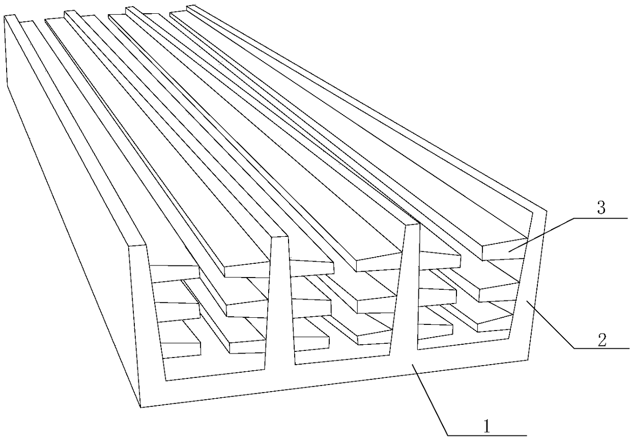
[0019] Such as figure 1 As shown, a heat dissipation structure for a cavity filter of the present invention includes a housing 1, heat sinks 2 evenly distributed on the outer surface of the housing 1, and auxiliary heat sinks 3 located on both sides of the heat sink 2, A plurality of auxiliary heat sinks 3 are evenly distributed on both sides of the heat sink 2. A heat sink 2 and a plurality of auxiliary heat sinks 3 on the heat sink form a heat dissipation unit. There is a gap between the heat dissipation units, and the gap distance is 0.5cm to 1cm. , the heat sink 2 and the auxiliary heat sink 3 are made of aluminum. During implementation, the height of the heat sink can be adjusted as required to enhance its heat dissipation performance. After increasing the height of the heat sink, a plurality of auxiliary heat sinks are added on both sides to increase the heat dissipation area and enhance its heat dissipation performance.


PUM


Abstract

The invention discloses a heat dissipation structure for a cavity filter. The heat dissipation structure comprises a shell, heat dissipation sheets uniformly distributed on the outer surface of the shell, and auxiliary heat dissipation sheets, wherein the auxiliary heat dissipation sheets are located on two sides of the heat dissipation sheets; multiple auxiliary heat dissipation sheets are uniformly distributed on two sides of the heat dissipation sheets; one heat dissipation sheet and the multiple auxiliary heat dissipation sheets on the heat dissipation sheet form one heat dissipation unit;a gap is reserved between the heat dissipation units; the gap is 0.5 to 1 cm; and the heat dissipation sheets and the auxiliary heat dissipation sheets are made of aluminum. The heights of the heat dissipation sheets are adjusted as required, so as to improve the heat dissipation performance of the heat dissipation structure; and after the heat dissipation sheets are heightened, the multiple auxiliary heat dissipation sheets are additionally arranged on the two sides to enlarge a heat dissipation area, so that the heat dissipation performance of the heat dissipation structure is improved.

Description

technical field [0001] The invention relates to a filter, in particular to a heat dissipation structure for a cavity filter. Background technique [0002] With the development and progress of electronic technology, the simple circuit structure can no longer meet the needs. Today's circuit structure is becoming more and more complex, and more and more electronic products require more and more data to be transmitted, making the system structure more and more complicated. Therefore, the design of the heat dissipation system is getting more and more attention. Faced with this development trend, it is inevitable to design a new type of heat dissipation device. Contents of the invention [0003] The technical problem to be solved by the present invention is that the current structure of the heat sink of the filter cannot meet the complex circuit structure of today. Problems with complex circuit structures. [0004] The present invention realizes through following technical sc...

Claims


Application Information

Patent Timeline
IPC IPC(8): H05K7/20H01P1/207H01P1/30
CPCH05K7/20409H01P1/207H01P1/30
Inventor 罗志刚王东宋旭
Owner CHENGDU XUSITE TECH CO LTD
Why Eureka
Try Eureka