
Precision positioning device of manipulator for L-shaped high-pressure pipe joint feeding

A technology of precise positioning and high-pressure tubes, applied in manipulators, program-controlled manipulators, metal processing, etc., can solve the problems that manipulators are not suitable for manual operation, the range of manipulator activities is fixed, and the composition and splicing are cumbersome, so as to increase the range of lateral activities and increase The effect of vertical range of motion and easy operation of the device

Inactive Publication Date: 2018-09-11
NANTONG AMC MACHINERY
View PDF6 Cites 5 Cited by
  • Summary
  • Abstract
  • Description
  • Claims
  • Application Information

AI Technical Summary

Problems solved by technology

[0002] High-pressure pipe joints are needed when the direction of the high-pressure pipe is changed. The high-pressure pipe joints are divided into L-type, T-type, etc. The L-type high-pressure pipe joints will involve feeding robots in the manufacturing process. It is a precise positioning device for L-shaped high-pressure pipe joints with a manipulator; the existing precise positioning device has certain disadvantages when it is used, it is not easy to carry, and the composition and splicing are relatively cumbersome, and the range of motion of the manipulator is fixed. The feeding machine is at the same height, and the traditional manipulator with positioning device is not suitable for manual operation. Therefore, we propose a precise positioning device for the manipulator for L-shaped high-pressure pipe joint feeding.

Method used


Image

  • Precision positioning device of manipulator for L-shaped high-pressure pipe joint feeding
  • Precision positioning device of manipulator for L-shaped high-pressure pipe joint feeding
  • Precision positioning device of manipulator for L-shaped high-pressure pipe joint feeding

Examples


Embodiment Construction

[0017] In order to make the technical means, creative features, goals and effects achieved by the present invention easy to understand, the present invention will be further described below in conjunction with specific embodiments.

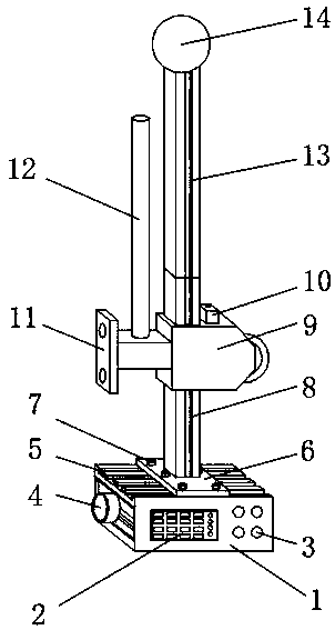
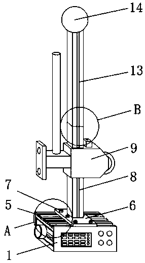
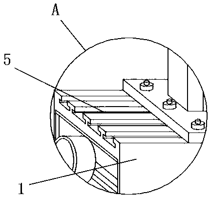
[0018] Such as Figure 1-5 As shown, an L-shaped high-pressure pipe joint feeding manipulator precise positioning device includes a locator main body 1 and a sliding seat 9. The outer surface of the front end of the locator main body 1 is fixedly mounted with a driving data interface 2, and the driving data interface 2 One side of the outer surface is provided with an indicator light 3, one end of the outer surface of the main body of the locator 1 is fixedly installed with a positioning probe 4, and the outer upper end of the main body of the locator 1 is fixedly installed with a T-shaped rail 5, above the outer surface of the main body of the locator 1 There is a mounting plate 6, and the outer upper end of the mounting plate 6 is fixedly instal...


PUM


Abstract

The invention discloses a precision positioning device of a manipulator for L-shaped high-pressure pipe joint feeding. The precision positioning device comprises a positioning indicator body and a sliding base; a drive data interface is fixedly installed on the outer surface of the front end of the positioning indicator body; an indicator light is arranged on one side of the outer surface of the drive data interface; a positioning probe is fixedly installed at one end of the outer surface of the positioning indicator body; a T-shaped rail is fixedly installed at the upper end of the outer surface of the positioning indicator body; a mounting plate is arranged above the outer surface of the positioning indicator body; and a fixed sliding rail is fixedly installed at the position, close to the middle, of the upper end of the outer surface of the mounting plate. The precision positioning device of the manipulator for L-shaped high-pressure pipe joint feeding is provided with the T-shapedrail, a movable sliding rail and the sliding base so that the precision positioning device can be carried, assembled and spliced conveniently, the movement range of the manipulator can be extended conveniently, and the precision positioning device is suitable for manual operation, suitable for different working conditions and capable of bringing better application prospects.

Description

technical field [0001] The invention relates to the field of precise positioning devices, in particular to a precise positioning device for a manipulator for loading L-shaped high-pressure pipe joints. Background technique [0002] High-pressure pipe joints are needed when the direction of the high-pressure pipe is changed. The high-pressure pipe joints are divided into L-type, T-type, etc. The L-type high-pressure pipe joints will involve feeding robots in the manufacturing process. It is a precise positioning device for L-shaped high-pressure pipe joints with a manipulator; the existing precise positioning device has certain disadvantages when it is used, it is not easy to carry, and the composition and splicing are relatively cumbersome, and the range of motion of the manipulator is fixed. The loading machine is at the same height, and the traditional manipulator with positioning device is not suitable for manual operation. Therefore, we propose a precise positioning devi...

Claims


Application Information

Patent Timeline
IPC IPC(8): B23P19/00B25J9/10
CPCB23P19/00B23P19/007B25J9/10
Inventor 戚顺平凌圣军梁松千冯克明唐玉芝
Owner NANTONG AMC MACHINERY
Learn More