Cloth tentering and sizing device

A stenter setting and cloth technology, which is applied in the direction of heating/cooling fabrics, textiles and papermaking, fabric surface trimming, etc., can solve the problems of uneven cloth surface, lifting page edge, uneven force on cloth, etc. Keep the effect of flatness and uniform force

Inactive Publication Date: 2018-09-11
宁波希奇服饰有限公司
View PDF4 Cites 4 Cited by
  • Summary
  • Abstract
  • Description
  • Claims
  • Application Information

AI Technical Summary

Problems solved by technology

[0003] The present invention intends to provide a cloth tentering and setting device to overcome the uneven force on the cloth during the drying process of the tentering machine in the prior art, which causes the cloth surface to be uneven and the edge to be raised. fringe question

Method used


Image

  • Cloth tentering and sizing device
  • Cloth tentering and sizing device
  • Cloth tentering and sizing device

Examples


Embodiment Construction

[0016] The present invention will be further described in detail below through specific implementations:

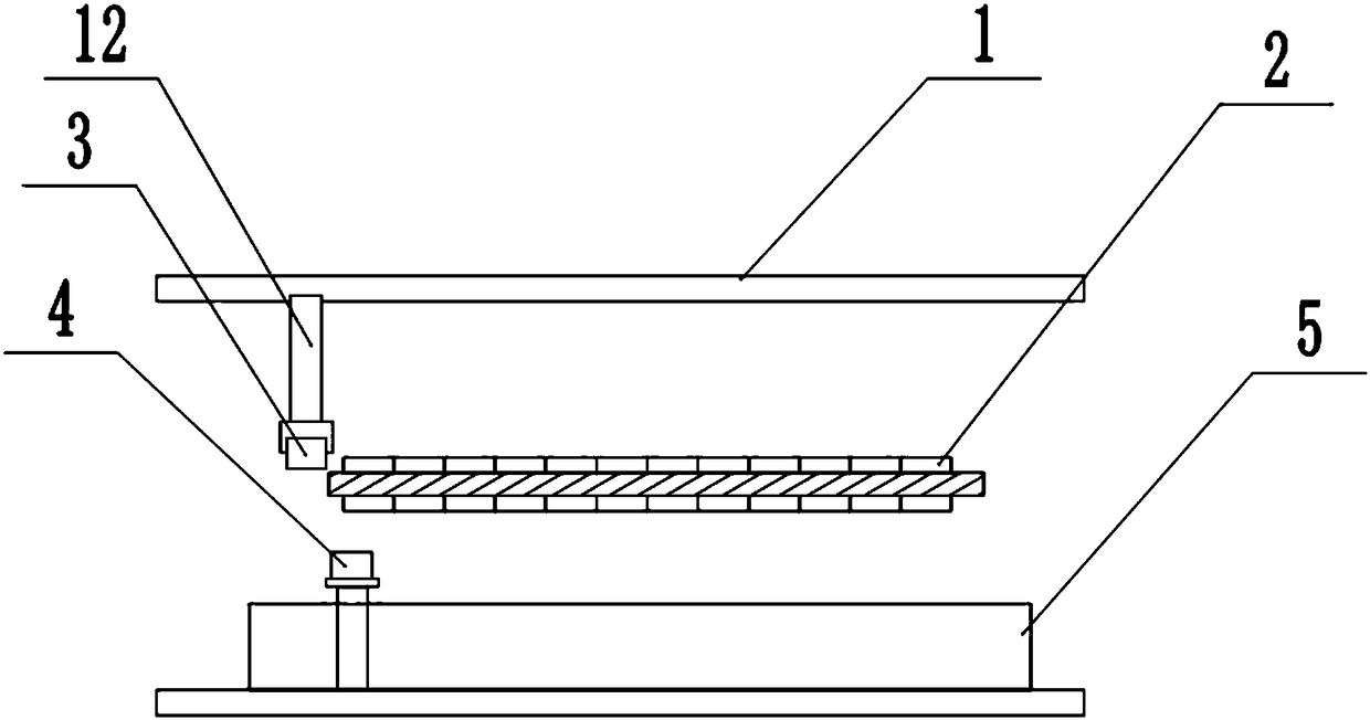
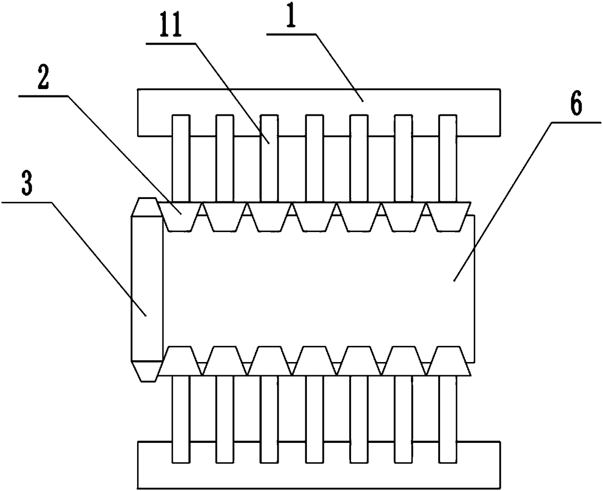
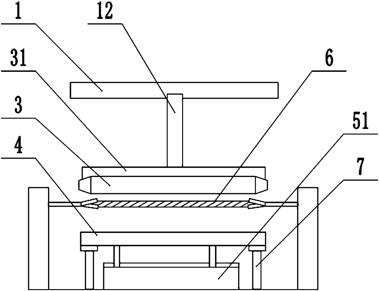
[0017] The reference signs in the drawings of the specification include: frame 1, push rod 11, sliding rod 12, clamping device 2, upper clamping piece 21, lower clamping piece 22, torsion spring 23, ejector 24, elongated magnet 3. Support 31, long iron block 4, open storage box 5, baffle 51, cloth 6, and telescopic frame 7.

[0018] The embodiment is basically as attached Figure 1 to 4 Shown: a fabric tentering setting device includes a frame 1, a plurality of push rods 11 are slidably installed on both sides of the frame 1, and the push rods 11 are connected with a clamping device 2 for clamping the fabric 6, so The frame 1 is slidably connected with a sliding rod 12, the sliding rod 12 is connected with a support, and the support is provided with an elongated magnet 3, and the elongated magnet 3 is located above the clamping device 2; An elongated iron block 4 is arranged...


PUM


Abstract

The invention relates to the technical field of textile machinery, and discloses a cloth tentering and sizing device which comprises a rack. A plurality of push rod are slidably arranged on the rack;clamping devices are connected to the end parts of the push rods; a slide rod is slidably arranged above the rack; an elongated magnet is arranged on the end part of the slide rod; an elongated iron block corresponding to the elongated magnet is also arranged in the rack. A cloth is clamped through the clamping devices, the slide rod above the rack is pushed to move, the elongated magnet moves synchronously, the elongated iron block and the elongated magnet are attracted with each other under the action of a magnetic force, the cloth is clamped between the elongated magnet and the elongated iron block, the elongated magnet and the elongated iron block produce a uniform extrusion force on the cloth, two ends of the elongated magnet extrude the clamping device during a continuous elongated magnet moving process, and the clamping devices are used for tentering and sizing the clamped cloth parts, so that each part of the cloth is stressed by a longitudinal uniform extrusion force and is subjected to the horizontal tentering and sizing action, and the cloth cover is kept flat.

Description

Technical field [0001] The invention relates to the technical field of textile machinery, in particular to a fabric tentering device. Background technique [0002] The traditional stenter setting machine only uses felting needles to fix the two sides of the fabric. The force on both sides of the product is large and the middle is in a suspended state. The force is small, which easily causes the fabric to have different width positions during the stenter drying process. The uneven force of the cloth will eventually cause appearance problems such as uneven cloth surface and ruffled edges. Summary of the invention [0003] The present invention intends to provide a fabric stenter setting device to overcome the uneven force on the fabric during the unexpected stenter drying process of the existing stenter setting machine, which makes the cloth surface uneven and edges rise. The problem of ruffles. [0004] To achieve the above objective, the basic solution of the present invention is ...

Claims


Application Information

Patent Timeline
Patent Type & Authority Applications(China)
IPC IPC(8): D06C3/00D06C7/02
CPCD06C3/00D06C7/02
Inventor 孙九荣
Owner 宁波希奇服饰有限公司
Why Eureka
Try Eureka