Thermal insulation ceiling of cement building

A building and cement technology, applied in the field of heat-insulated roofs, can solve the problems of inconvenient disassembly and assembly of solid awnings, affect lighting, block vision, etc., achieve the effects of reducing investment costs, facilitating installation and disassembly, and preventing collapse

Active Publication Date: 2018-09-11
FOSHAN UNIVERSITY
View PDF7 Cites 3 Cited by
  • Summary
  • Abstract
  • Description
  • Claims
  • Application Information

AI Technical Summary

Problems solved by technology

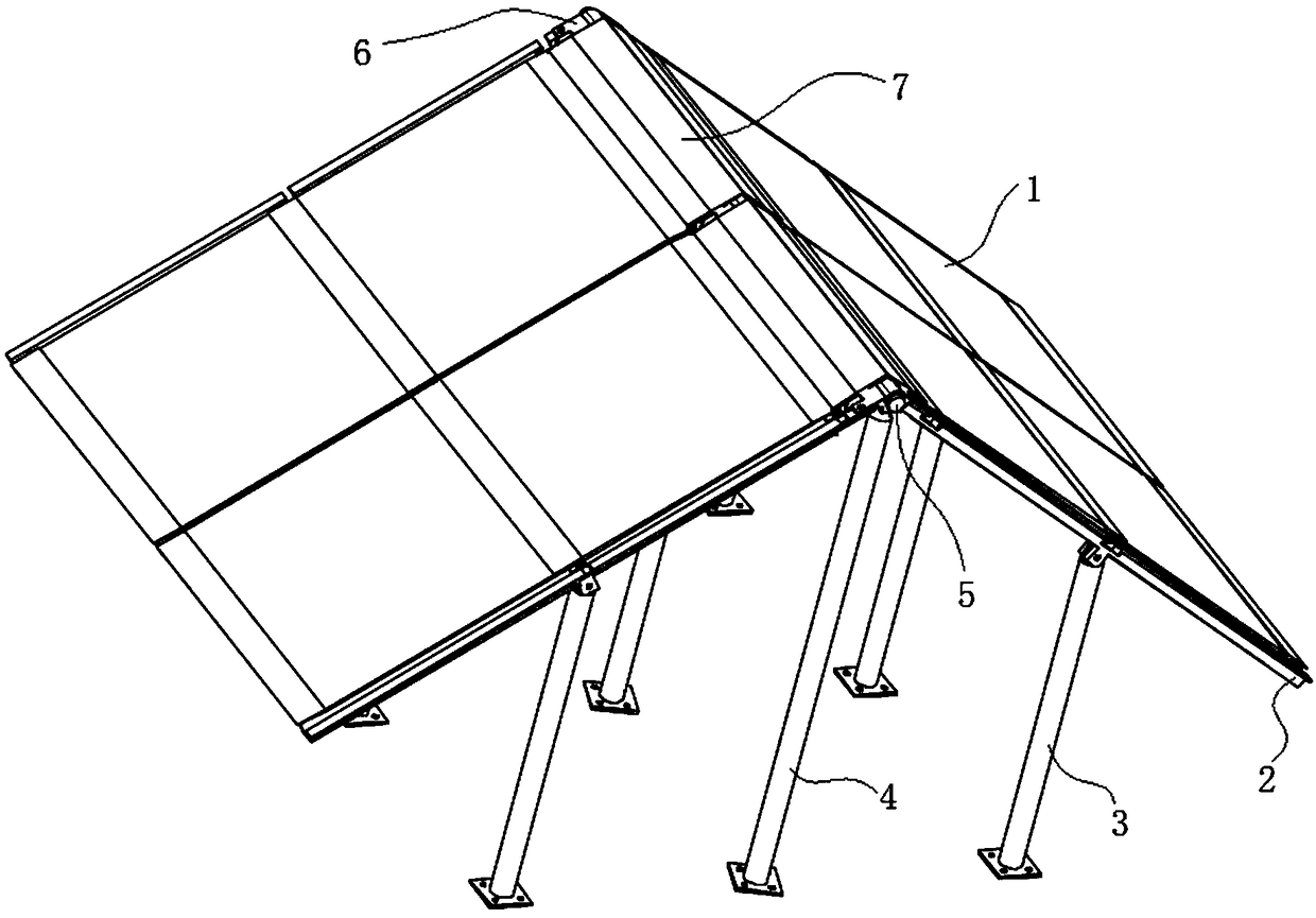
[0006] The purpose of the present invention is to provide a heat-insulating roof of a cement building. By changing the structure of the heat-insulating board of the solid sunshade, it solves the problems of inconvenient disassembly and assembly of the existing solid sunshade, affecting daylighting, and blocking the view.

Method used


Image

  • Thermal insulation ceiling of cement building
  • Thermal insulation ceiling of cement building
  • Thermal insulation ceiling of cement building

Examples


Embodiment Construction

[0031] The following will clearly and completely describe the technical solutions in the embodiments of the present invention with reference to the accompanying drawings in the embodiments of the present invention. Obviously, the described embodiments are only some of the embodiments of the present invention, not all of them. Based on the embodiments of the present invention, all other embodiments obtained by persons of ordinary skill in the art without creative efforts fall within the protection scope of the present invention.

[0032] In describing the present invention, it is to be understood that the terms "opening", "upper", "lower", "thickness", "top", "middle", "length", "inner", "surrounding" etc. Indicating orientation or positional relationship is only for the convenience of describing the present invention and simplifying the description, and does not indicate or imply that the components or elements referred to must have a specific orientation, be constructed and op...


PUM


Abstract

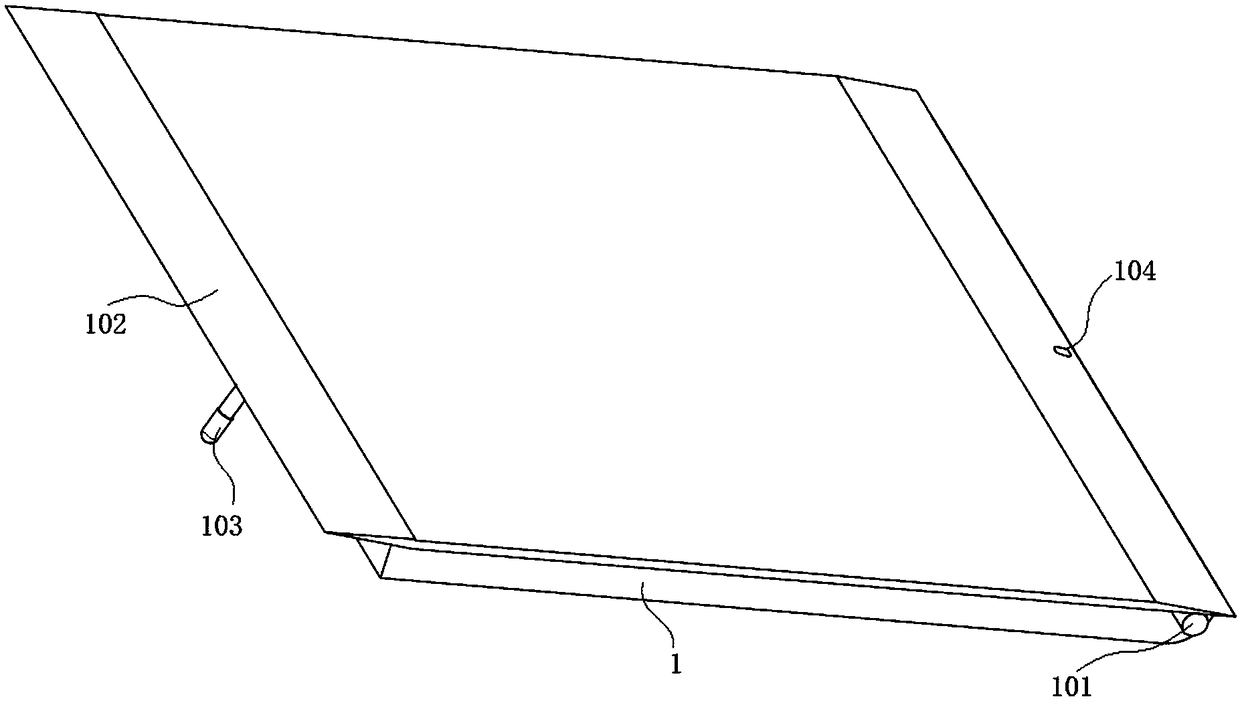
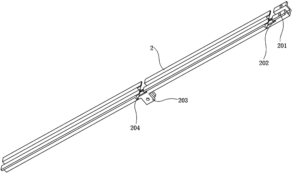
The invention discloses a thermal insulation ceiling of a cement building and relates to the technical field of construction. The thermal insulation ceiling comprises thermal insulation plates, crossbeams, main supporting rods, auxiliary supporting rods, a main rod, a connecting cylinder and a top cover; the main rod is matched with the connecting cylinder; a connecting casing is fixed to the circumferential side face of the connecting cylinder; multiple connecting plates are fixed to the circumferential side face of the connecting cylinder; the main rod is matched with the top cover; a clamping groove is formed in the inner surface of the top cover; the connecting plates are matched with the cross beams; a connection base is fixed to one surface of each cross beam; each second groove isformed in one surface of the corresponding cross beam; the second grooves are matched with the thermal insulation plates; multiple connecting columns are fixed to the circumferential side faces of thethermal insulation plates; a retractable rod is fixed to one surface of each thermal insulation plate, and a third groove is formed in one surface of each thermal insulation plate. By using the smallcombined-type thermal insulation plates, clamping connection and sleeving connection are adopted on multiple parts, convenience is provided for installation and dismantling, and the thermal insulation plates can be recycled; the thermal insulation plates can be adjusted, the maximum adjustment angle is 90 degrees, and the problems that existing solid sunshades are inconvenient to disassemble andassemble, influence lighting and block the view are solved.

Description

technical field [0001] The invention belongs to the technical field of buildings, in particular to a thermal insulation roof of a cement building. Background technique [0002] Now there are many two- to three-story buildings in rural construction. The buildings use ordinary construction methods without heat insulation. Every summer, the top floor is hot and unbearable. To solve this problem, the following two methods are usually used: [0003] 1. Air circulation can take away heat. Therefore, a heat insulation layer can be laid on the roof. The sun shines directly on the heat insulation layer. This is a traditional and effective heat insulation method. [0004] 2. In recent years, heat insulation of awnings has become popular, and awnings are divided into mesh sheds and solid sheds. [0005] Existing solid awnings usually use large plates, which are inconvenient to install and cannot be recycled, so the construction cost is high; at the same time, it affects lighting and ...

Claims


Application Information

Patent Timeline
Patent Type & Authority Applications(China)
IPC IPC(8): E04B7/02
CPCE04B7/024
Inventor 史亮何凌峰王军飞郑月云
Owner FOSHAN UNIVERSITY
Why Eureka
Try Eureka