Hydraulic interlocking control system

A control system and hydraulic technology, applied in the direction of fluid pressure actuation system safety, fluid pressure actuation system components, fluid pressure actuation device, etc., can solve misoperation accidents, cost huge financial resources and manpower, and equipment damage crisis site personnel life safety issues

Active Publication Date: 2018-09-11
上海朗畏液压股份有限公司
View PDF7 Cites 2 Cited by
  • Summary
  • Abstract
  • Description
  • Claims
  • Application Information

AI Technical Summary

Problems solved by technology

This kind of controller is prone to misoperation. If it is used for a long time, misoperation accidents will occur. Misoperation will cause serious damage to the equipment and endanger the lives of personnel on site. Subsequent remedies will cost huge financial resources and manpower.
Hydraulic and electrical control can achieve interlocking, but it cannot be used in explosion-proof conditions where the use of electricity is prohibited

Method used


Image

  • Hydraulic interlocking control system
  • Hydraulic interlocking control system
  • Hydraulic interlocking control system

Examples


Embodiment 1

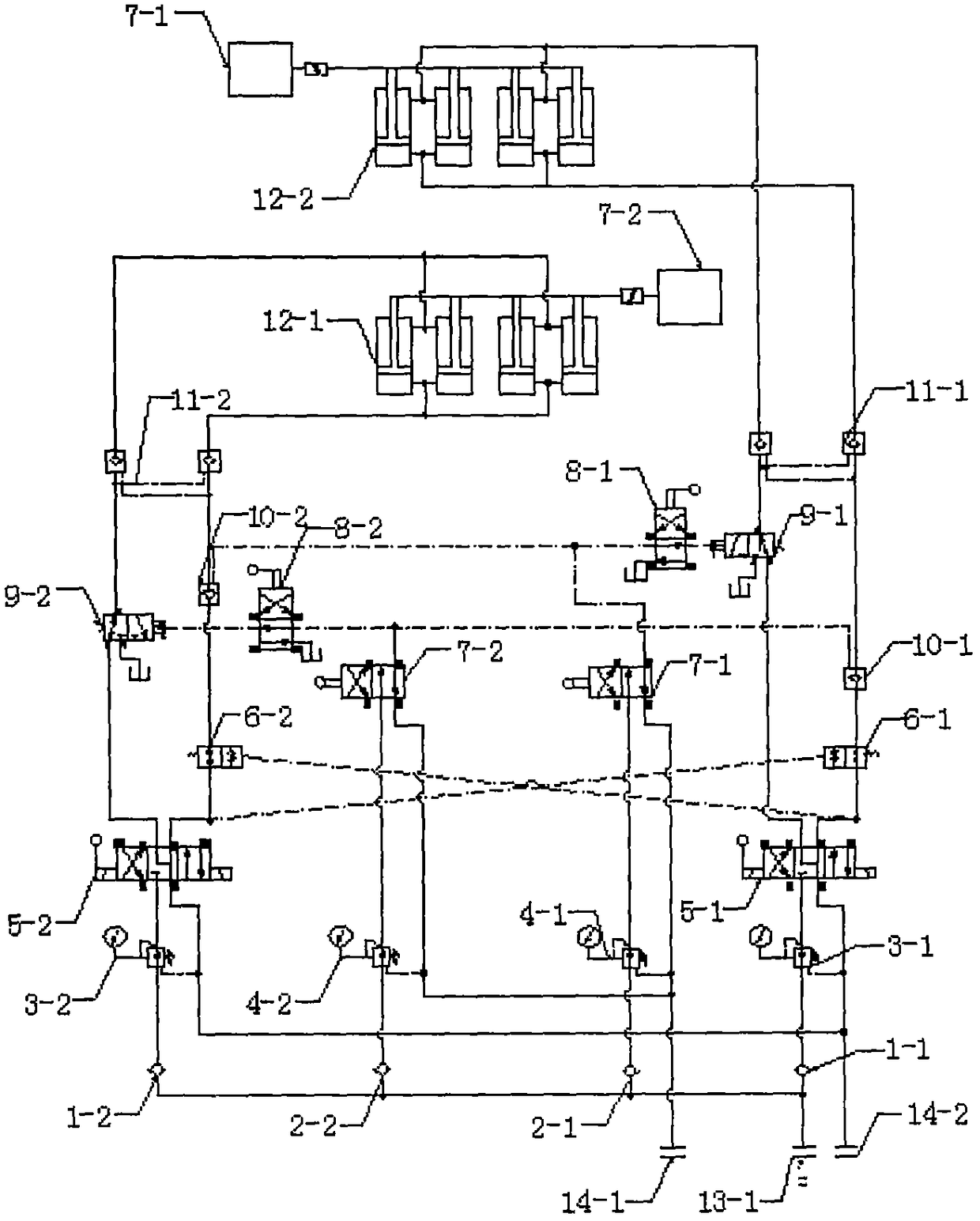
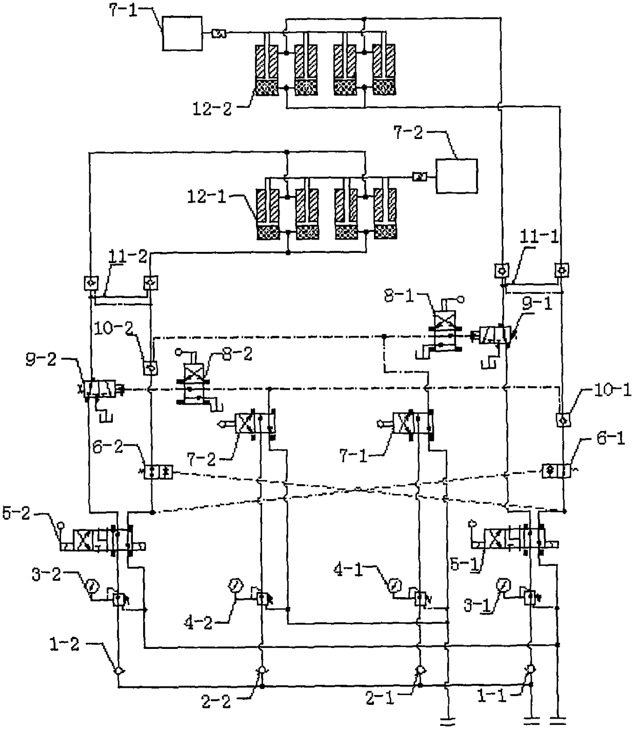
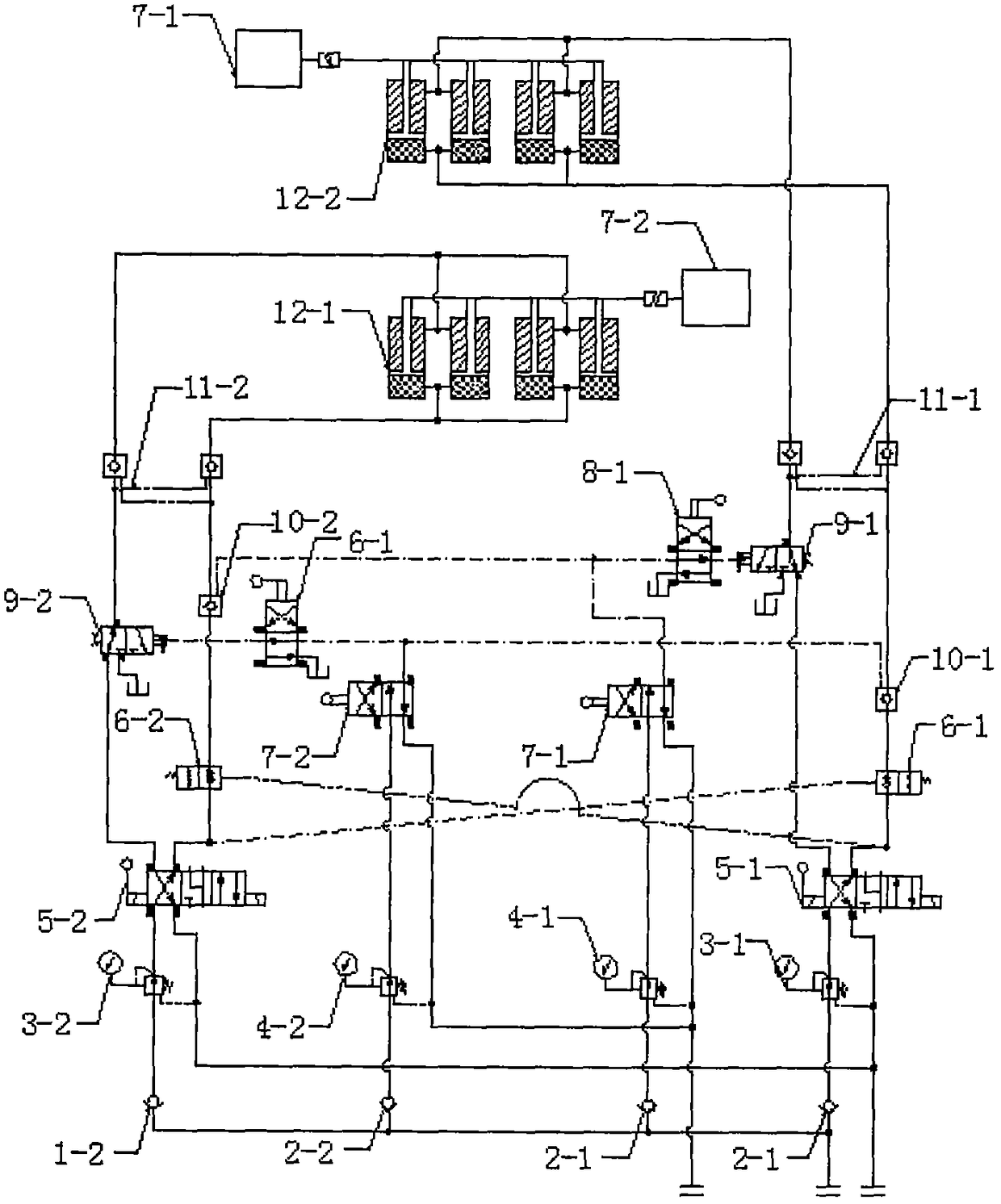
[0015] like Figure 1-3 As shown, the present invention provides a hydraulic interlock control system, including oil cylinder A12-1, oil cylinder B12-2, oil inlet 13-1, oil outlet A14-1 and oil outlet B14-2, oil inlet 13-1 is connected to the oil cylinder A12-1 through the first oil delivery pipe, the oil inlet 13-1 is connected to the oil cylinder B12-2 through the second oil delivery pipe, and the oil outlet B14-2 is connected to the oil cylinder A12-1 through the first oil return pipe. The oil port B14-2 is connected to the oil cylinder B12-2 through the second oil return pipe, and the connection between the first oil delivery pipe and the first oil return pipe is installed with a pressure reducing valve A3-1, a manual valve A5-1 and a hydraulic control check valve C11- 1. The first oil delivery pipe is connected to the second oil return pipe through logic valve C9-1, manual valve C8-1 and hydraulic control check valve B10-2; a pressure reducing valve B3 is installed betwee...


PUM


Abstract

The invention discloses a hydraulic interlocking control system comprising an oil cylinder A and an oil cylinder B. An oil inlet is connected with the oil cylinder A through a first oil delivery pipeand is connected with the oil cylinder B through a second oil delivery pipe. An oil outlet A is connected with the oil cylinder A through a first oil return pipe. An oil outlet B is connected with theoil cylinder B through a second oil return pipe. A pressure reducing valve A, a manual valve A and a hydraulic control one-way valve C are connected and installed between the first oil delivery pipeand the first oil return pipe. The first oil delivery pipe is connected with the second oil return pipe through a logical valve C, a manual valve C and a hydraulic control one-way valve B. A pressurereducing valve B, a manual valve B and a hydraulic control one-way valve D are installed between the second oil delivery pipe and the second oil return pipe. The second oil delivery pipe is connectedwith the first oil return pipe through a logical valve D, a manual valve D and a hydraulic control one-way valve A. The first oil return pipe is connected with the second oil return pipe through a logical valve A. The second oil return pipe is connected with the first oil return pipe through a logical valve through a logical valve B. The hydraulic interlocking control system is high in safety andwide in application range.

Description

technical field [0001] The invention relates to a control system, in particular to a hydraulic interlock control system, which belongs to the technical field of hydraulic equipment. Background technique [0002] At present, the general hydraulic interlock realizes the interlock function through hydraulic plus limit switch, contact switch, button, displacement sensor and other electrical signaling devices combined with electrical control, or operates the hydraulic reversing valve step by step through the prescribed operation process. This kind of controller is prone to misoperation. If it is used for a long time, misoperation accidents will occur. Misoperation will cause serious damage to the equipment and endanger the lives of personnel on the scene. Subsequent remedies will cost huge financial and manpower. Hydraulic and electrical control can achieve interlock, but it cannot be used in explosion-proof conditions where the use of electricity is prohibited. Contents of the...

Claims


Application Information

Patent Timeline
IPC IPC(8): F15B20/00F15B21/00F15B11/16F15B13/06
CPCF15B11/16F15B13/06F15B20/00F15B21/001
Inventor 杨乐乐陈东
Owner 上海朗畏液压股份有限公司
Why Eureka
Try Eureka