
Luminous collaboration sign videogrammetric method based on time coding

A technology of time coding and camera measurement, which is applied in the field of camera measurement and computer vision, can solve the problems of restricting other applications of cameras, and achieve the effects of fast detection speed, strong engineering practicability, and good anti-interference ability

Inactive Publication Date: 2018-09-11
NAT UNIV OF DEFENSE TECH
View PDF4 Cites 0 Cited by
  • Summary
  • Abstract
  • Description
  • Claims
  • Application Information

AI Technical Summary

Problems solved by technology

Selecting luminous signs of specific bands such as infrared can improve the anti-interference ability of the system to a certain extent, but a filter corresponding to the band in front of the camera lens is required, which makes the camera only sensitive to a certain band, which limits some other applications of the camera

Method used


Image

  • Luminous collaboration sign videogrammetric method based on time coding
  • Luminous collaboration sign videogrammetric method based on time coding
  • Luminous collaboration sign videogrammetric method based on time coding

Examples


Embodiment Construction

[0014] 1. Luminous cooperation logo time code

[0015] The time coding of the patent of the present invention means that the brightness of different parts of the luminous cooperation sign will change regularly with time, and the specific implementation can be implemented by using the control circuit to control the on-off time of the power supply and the changes in the strength of voltage and current;

[0016] When controlling different parts to emit light, each part should be a module that can emit light and supply power independently. If the luminous cooperation sign is composed of multiple luminous sign lights (as attached figure 1 As shown), each marker lamp can be independently powered and illuminated independently, and each marker lamp can be used as a different part of the luminous cooperation sign. Taking the luminous cooperation sign composed of multiple sign lights as an example, the time code can be designed in the following forms: 1) The power control circuit contr...


PUM


Abstract

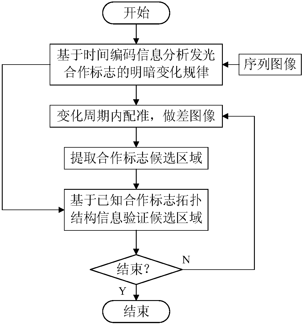
The invention relates to a luminous collaboration sign videogrammetric method based on time coding. In the video measurement, the collaboration signs are time-coded luminous signs. Luminous parts andluminous intensity of the collaboration signs are periodically changed with time according to settings. With the changing rule, coding of time is formed. in the video measurement, continuous imaging of a collaboration sign is realized through a camera, the collaboration sign in the images is detected and traced according to the sign luminous time coding rule, and relative pose video measurement iscarried out according to a video measurement model. By time coding mode for design of the luminous collaboration signs, interference of complex background is eliminated. The method of the invention has good resistance to interference and has high use value and engineering meaning.

Description

technical field [0001] The present invention belongs to the field of computer vision and camera measurement. Specifically, the invention designs a new camera measurement method, which improves the anti-interference ability of cooperation sign detection in computer vision or camera measurement by time encoding the luminous cooperation signs. The camera measurement under complex background conditions is realized. Background technique [0002] Computer vision-based photogrammetry refers to the use of cameras to capture target images, and to calculate the position and attitude of the target camera relative to the camera through relevant information. In order to improve the accuracy and speed of measurement, cooperation signs with known positions are usually arranged on the target. Cooperative markers are also called cooperative targets, that is, artificial targets whose shape, size, and relative positional relationship are known. Pose measurement based on cooperation marks has...

Claims


Application Information

Patent Timeline
IPC IPC(8): G01C11/12
CPCG01C11/12
Inventor 张红良王梓尚洋
Owner NAT UNIV OF DEFENSE TECH
Learn More