Supercharge Your Innovation With Domain-Expert AI Agents!

Adjusting device and control method for resonant converter based on additional coupled inductance

A resonant converter and additional coupling technology, applied in the direction of circuit devices, electrical components, etc., to achieve the effect of large-scale adjustment and easy control

Active Publication Date: 2020-08-14
NANJING UNIV OF AERONAUTICS & ASTRONAUTICS
View PDF3 Cites 0 Cited by
  • Summary
  • Abstract
  • Description
  • Claims
  • Application Information

AI Technical Summary

Problems solved by technology

[0011] The technical problem to be solved by the present invention is: the problem of dynamic tuning of resonant converters such as non-contact resonant converters under various variable parameters such as load changes, primary and secondary side position changes, and environmental changes.

Method used


Image

  • Adjusting device and control method for resonant converter based on additional coupled inductance
  • Adjusting device and control method for resonant converter based on additional coupled inductance
  • Adjusting device and control method for resonant converter based on additional coupled inductance

Examples


Embodiment 1

[0058] attached as Figure 13 As shown, the adjustment device for resonant converter with additional coupling inductor (hereinafter referred to as the adjustment device) includes a DC excitation unit 001a, an inverter unit 001b, an LC resonant network 001c, and an additional coupling inductor 003, where 001a, 001b, and 001c are jointly composed of The excitation source 001 and the controller 002 are not shown, which are specifically included in the attached Figure 14 middle.

[0059] attached Figure 14 It is a schematic diagram of the overall structure of the system using this regulating device when the main circuit transformer is LCL / P compensation in this embodiment. As shown in the figure, the main circuit includes: a main circuit DC excitation source 101a, a main circuit inverter 101b, and a main circuit Primary side compensation 101c, main circuit transformer 101d, main circuit secondary side compensation 101e, main circuit rectifier 101f, main circuit filter 101g, ma...

Embodiment 2

[0083] The adjusting device for the resonant converter based on the additional coupling inductance used in this embodiment is shown in the attached Figure 13 shown.

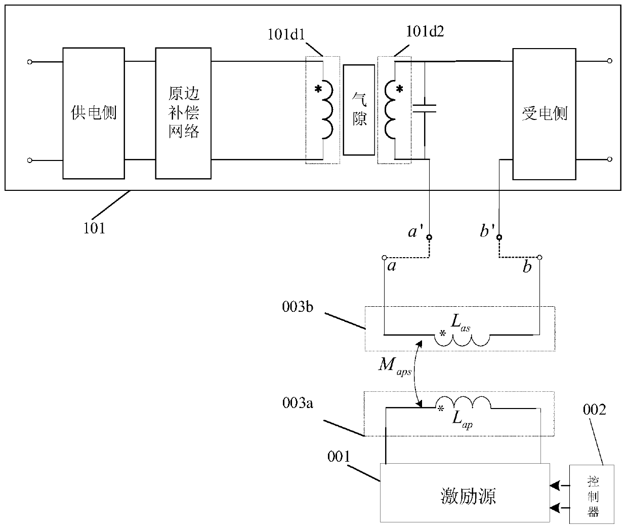
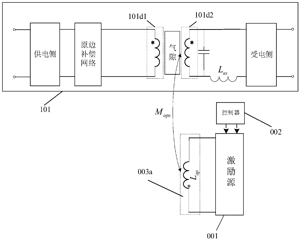
[0084] attached Figure 15 It is a schematic diagram of the overall structure of the system using this regulating device in this embodiment. As shown in the figure, the main circuit includes: a main circuit DC excitation source 101a, a main circuit inverter 101b, a main circuit primary side compensation 101c, and a main circuit transformer 101d , main circuit secondary side compensation 101e, main circuit rectifier 101f, main circuit filter 101g, main circuit load 101h, 101a (001a is shared with the main circuit DC excitation source), 001b, 001c, 002, and 003 together form a regulating device. The secondary winding of the additional coupled inductor is connected in series with the primary winding 101d1 of the main circuit (that is, connected in series between 101c and 101d1), and the primary winding of the addi...

Embodiment 3

[0108] The adjusting device for the resonant converter based on the additional coupling inductance used in this embodiment is shown in the attached Figure 13 shown.

[0109] attached Figure 16 It is a schematic diagram of the overall structure of the system using this regulating device in this embodiment. As shown in the figure, the main circuit includes: main circuit DC excitation source 101a, main circuit inverter 101b, main circuit primary side compensation 101c, main circuit transformer 101d, main circuit secondary side compensation 101e, main circuit rectifier 101f, main circuit filter 101g, main circuit load 101h, 001a, 001b, 001c, 002, 003 together form a regulating device. , the compensation topology of the main circuit part in this embodiment is still taking series / parallel compensation (S / P) as an example, which is different from Embodiment 1 and Embodiment 2. In this embodiment, the adjustment device adopts an independent DC excitation source 001a, and an additio...


PUM


Abstract

The invention discloses a regulating device used for a resonant converter and based on an additional coupling inductance and a control method thereof. The regulating device comprises an excitation source and a controller and also comprises an additional coupling inductance, wherein the excitation source is connected with a primary side of the additional coupling inductance, and a secondary side ofthe additional coupling inductance is connected with any branch circuit of the primary side and / or secondary side of a to-be-regulated main circuit in series and / or parallel. The regulating device disclosed by the invention has the advantages that control is simple, a strong item is controlled by a weak item, and tuning of any detuning circuit and / or regulation of output voltage, current, power and system efficiency are / is realized by virtue of relatively small current excitation by adopting an additional coupling inductance manner.

Description

technical field [0001] The present invention relates to power electronics technology, non-contact power transmission technology, and control technology of non-contact power transmission system, in particular to an adjustment device and control method based on additional coupling inductance. Background technique [0002] Resonant converters are widely used in the field of power conversion, but the aging and temperature drift of resonant components (L, C) will lead to changes in system circuit parameters, resulting in circuit detuning, gain changes, reduced efficiency, increased device stress, and power handling. Reduced capacity and reduced reliability. On the other hand, in some applications, it is required or hoped that the size (inductive reactance, capacitive reactance) of some resonant elements in the variator can be changed as the working conditions of the system change, so as to improve the working performance of the system. [0003] Taking the resonant converter unde...

Claims


Application Information

Patent Timeline
Patent Type & Authority Patents(China)
IPC IPC(8): H02J50/12H02J50/80
CPCH02J50/12H02J50/80
Inventor 耿玉川陈乾宏高伟任小永张之梁
Owner NANJING UNIV OF AERONAUTICS & ASTRONAUTICS
Features
  • R&D
  • Intellectual Property
  • Life Sciences
  • Materials
  • Tech Scout
  • Unparalleled Data Quality
  • Higher Quality Content
  • 60% Fewer Hallucinations
Learn More