Drive unit for endoscopic cutting staplers

A driving device and a stapler technology, applied in the field of medical devices, can solve the problems of unstable switching function, complex structure, and inconvenient switching operation, and achieve the effects of improving operational reliability and comfort, large effective area, and convenient operation

Pending Publication Date: 2018-09-14
CHANGZHOU KANGDI MEDICAL STAPLER
View PDF0 Cites 6 Cited by
  • Summary
  • Abstract
  • Description
  • Claims
  • Application Information

AI Technical Summary

Problems solved by technology

[0006] In order to solve the problems existing in the prior art that the switching structure is arranged on the side of the casing, the structure is complicated, the switching operation is inconvenient and the switching function is unstable, the present invention provides a driving device for an endoscopic cutting stapler

Method used


Image

  • Drive unit for endoscopic cutting staplers
  • Drive unit for endoscopic cutting staplers
  • Drive unit for endoscopic cutting staplers

Examples


Embodiment 1

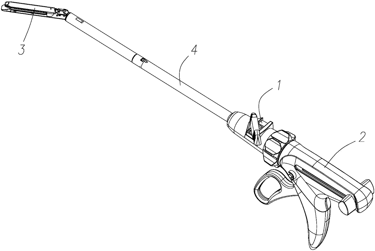
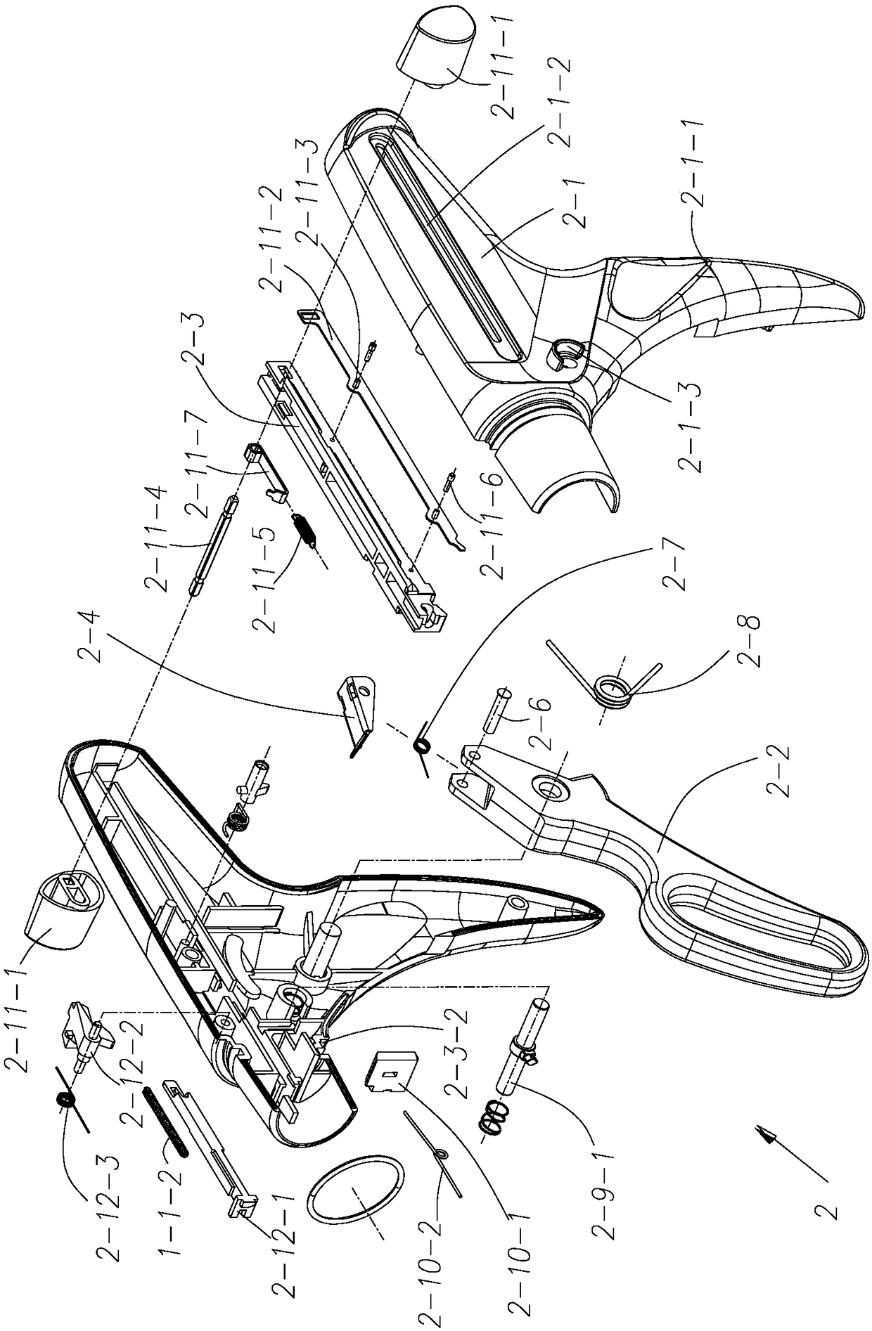
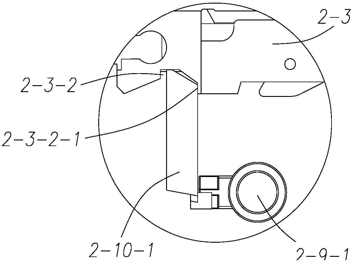
[0034] Such as Figure 6-11 As shown, a driving device for an endoscopic cutting stapler, the stapler includes a jaw assembly 3 and a sleeve assembly 4, the sleeve assembly 4 includes a driving rod 4-2, and the driving device 2 includes The housing 2-1, the trigger 2-2 provided on the housing 2-1 and the rack 2-3, the driving block 2-4 and the switching part 2-9 arranged in the housing 2-1, said The drive block 2-4 is connected between the trigger 2-2 and the rack 2-3, the drive block 2-4 is rotatably arranged on the trigger 2-2, and the front end of the drive block 2-4 has a -3 toothed paddle 2-4-1 (arm direction is rear, gun barrel direction is front), the driving device 2 also includes extension spring 2-5, and the bottom of the housing 2-1 has a handle 2-1-1, the rear end of the drive block 2-4 is provided with a pull hole 2-4-2, the pull hook at one end of the pull spring 2-5 is hooked into the pull hole 2-4-2, and the other end The drag hook hooks the bottom of the han...

Embodiment 2

[0045] This embodiment provides a laparoscopic cutting stapler, which includes a steering device 1 , a driving device 2 , a sleeve assembly 4 and a jaw assembly 3 according to the first embodiment.

[0046] Such as Figure 12As shown, the steering device 1 is fastened between the bushing assembly 4 and the driving device 2, the steering device 1 includes an upper rotary head 1-1, a knob 1-6 and a shift block 1-8, and the upper rotary head 1 -1 is provided with a shifting block groove 1-1-4, and the shifting block 1-8 is arranged in the shifting block groove 1-1-4, and the upper rotary head 1-1 is fixed with a knob rotating shaft 1-1-5, and the knob The 1-6 rotation sleeve is set on the knob shaft 1-1-5, and is axially limited on the knob shaft 1-1-5 by the knob pin 1-10, and there is a protruding shaft 1-6 extending below the knob 1-6 -3, there is a long slot 1-8-1 on the top of the shifting block 1-8 that matches the protruding shaft 1-6-3, when the knob 1-6 is turned, the p...

Embodiment 3

[0048] This embodiment provides a laparoscopic cutting stapler, which includes a steering device 1 , a driving device 2 , a sleeve assembly 4 and a jaw assembly 3 according to the first embodiment.

[0049] Such as Figures 13 to 18 As shown, the steering device 1 is fastened between the sleeve assembly 4 and the driving device 2, the steering device 1 includes an upper swivel head 1-1, and a steering cover extends outward on the upper swivel head 1-1 1-1-1, the steering cover 1-1-1 is integrated with the upper rotating head 1-1, the upper rotating head 1-1 is fastened with the lower rotating head 1-2; and the rotating shaft 1-3, The rotating shaft 1-3 is rotatably arranged on the upper rotating head 1-1, and the bottom end of the rotating shaft 1-3 has a limit disc 1-3-1; and a toothed plate 1-4, and the toothed plate 1- The outer circumference of 4 is extended outward with a card protrusion 1-4-2, and the upper rotary head 1-1 is provided with a bayonet 1-1-3 that cooperate...


PUM


Abstract

The invention belongs to the technical field of medical instruments and particularly relates to a drive unit for endoscopic cutting staplers. The drive unit comprises a shell, a trigger rotatably arranged on the shell and a rack, a drive block and a switching part which are arranged in the shell, the drive block is arranged on the trigger, the front end of the drive block is provided with a shiftpiece matched with the rack in tooth form, the drive block of the trigger is pulled to be matched with the rack to drive the rack to move forward, and the rack is connected with a jaw assembly througha drive rod; the switching part comprises a switching button arranged above the rear end of the shell and a switching limit block rotatably arranged in the shell, a limit long slot is formed in the rack, a switching torsional spring is arranged between the switching limit block and the shell, the switching torsional spring acts on the switching limit block to enable a boss at the rear end of theswitching limit block to be inserted in the limit long slot, a switching slope is arranged at the bottom of the switching button, the oblique plane of the switching slope pushes the boss to enable theswitching limit block to rotate when the switching button is pushed forward, and the boss is divorced from the limit long slot.

Description

technical field [0001] The invention belongs to the technical field of medical instruments, in particular to a driving device for an endoscopic cutting stapler. Background technique [0002] The laparoscopic cutting stapler suitable for minimally invasive surgery is a device that can nail a plurality of staggered staples on human tissue in a straight line, and at the same time cut off the tissue between the staple lines with a cutting knife , is also one of the instruments widely used in minimally invasive surgery, mainly used for tissue resection, transection and anastomosis in open or endoscopic surgery in abdominal surgery, gynecology, pediatrics and thoracic surgery. [0003] Such as Figure 1~5 As shown, the prior art laparoscopic cutting stapler includes a driving device 2, and the driving device 2 includes a housing 2-1 with a handle 2-1-1, and a trigger 2-2 that is rotated on the housing 2-1. And the rack 2-3 that is arranged in the housing 2-1 and the driving block...

Claims


Application Information

Patent Timeline
Patent Type & Authority Applications(China)
IPC IPC(8): A61B17/072A61B17/00
CPCA61B17/07207A61B17/00234A61B2017/07285
Inventor 王海涛杨卫民吉荣
Owner CHANGZHOU KANGDI MEDICAL STAPLER
Why Eureka
Try Eureka