Ultrahigh-speed horizontal band sawing machine

An ultra-high-speed, band sawing machine technology, used in sawing machine devices, metal sawing equipment, metal processing equipment, etc., can solve the problems of difficulty in high-speed operation, short service life, high noise, etc., to improve repeat accuracy and reliability, The effect of improving sawing accuracy and reducing power consumption

Pending Publication Date: 2018-09-14
昆山汉田机械工业有限公司
View PDF0 Cites 4 Cited by
  • Summary
  • Abstract
  • Description
  • Claims
  • Application Information

AI Technical Summary

Problems solved by technology

[0004] In order to overcome the above problems, the present invention provides an ultra-high-speed horizontal band sawing machine, which solves the problems that the traditional horizontal band sawing machine is difficult to meet the high-speed operation requirements, and the service life is short, the precision is poor, the efficiency is low, and the noise is large.

Method used


Image

  • Ultrahigh-speed horizontal band sawing machine
  • Ultrahigh-speed horizontal band sawing machine
  • Ultrahigh-speed horizontal band sawing machine

Examples


Embodiment

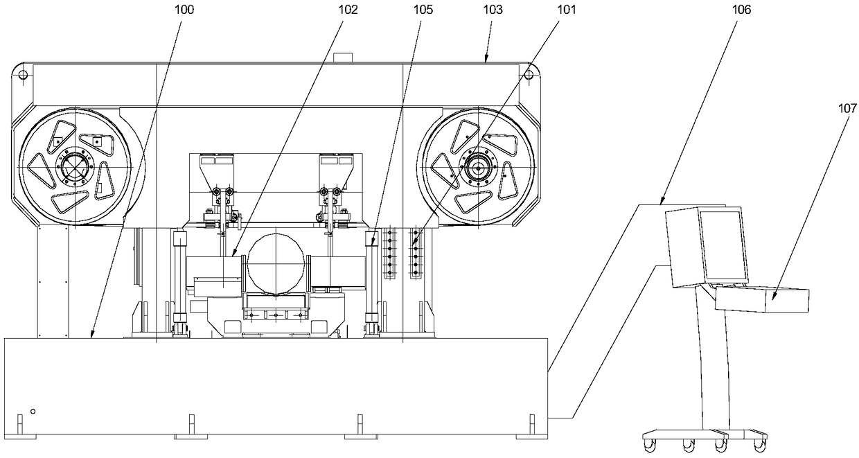
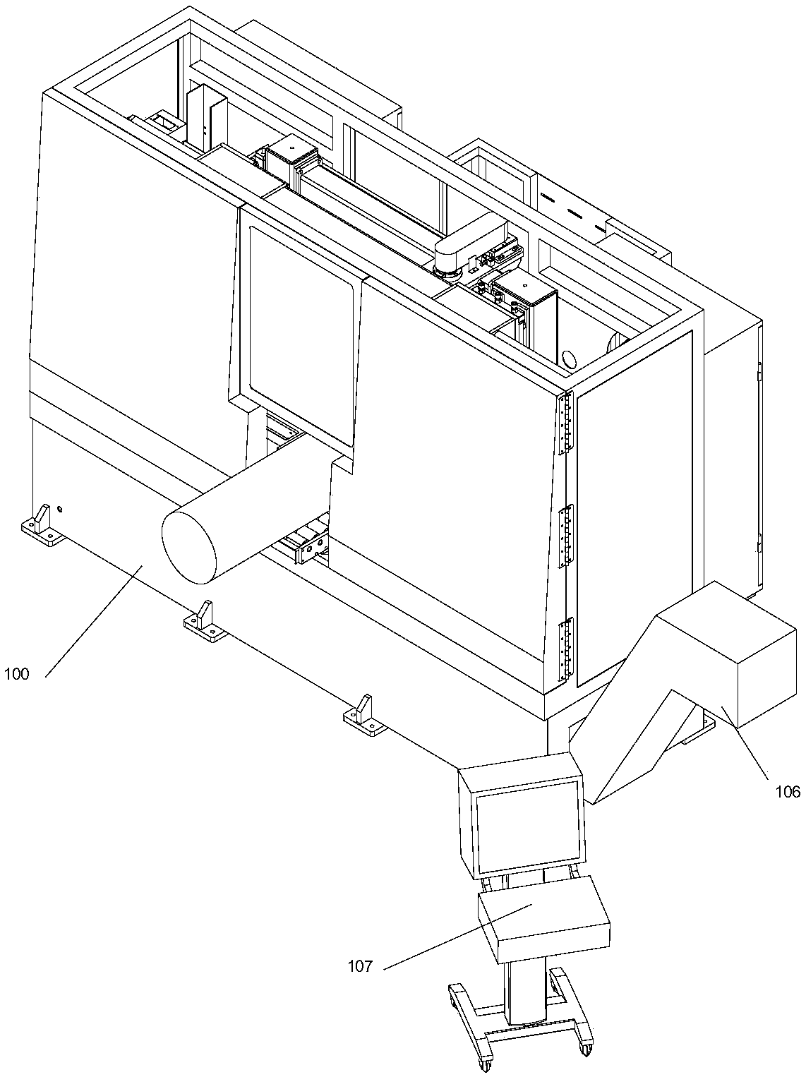
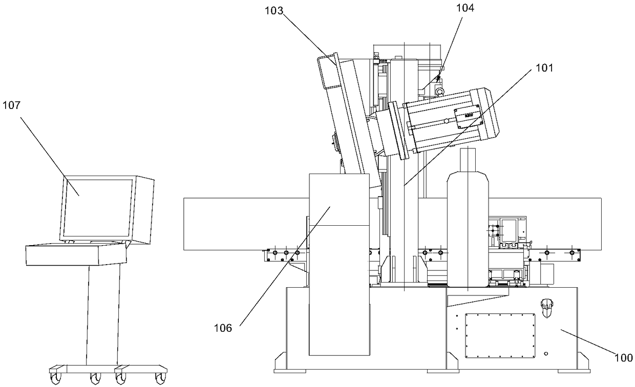
[0030] Please also refer to Figures 1 to 3 , an ultra-high-speed horizontal band sawing machine, including a base 100, a column 101, a bed 102, a saw frame 103, a servo drive system 104, a saw frame lifting and balancing system 105, a chip removal machine 106 and a controller 107. The saw frame 103 is inclined forward relative to the column 101, and its inclination angle is 12°.

[0031] Wherein, the bed platform 102 is installed on the base 100 for arranging and clamping sawing materials, and the columns 101 are arranged on the left and right sides of the bed platform 102 .

[0032] The saw frame 103 can be lifted up and down along the column 101, and it includes a driving wheel 91, a driven wheel 92, a saw band 93, a tensioning device 94, and a saw band guiding device 95 for turning and clamping the saw band. The saw band 93 is sheathed on the driving wheel 91 and the driven wheel 92 , and the tensioning device 94 is used to increase the distance between the driving wheel ...


PUM


Abstract

The invention discloses an ultrahigh-speed horizontal band sawing machine. The ultrahigh-speed horizontal band sawing machine comprises a base, a vertical column, a machine table and a sawing frame and further comprises a servo driving system and a sawing frame lifting balance system. The servo driving system comprises a servo motor, a decelerator and a ball lead screw. The decelerator is mountedon the vertical column, the ball lead screw is connected with the sawing frame, and the servo motor drives the sawing frame to rise and fall by driving the ball lead screw to rotate. The sawing framelifting balance system is used for reducing the axial linear load of the servo motor and provided with symmetrically arranged oil cylinders, a hose and an energy storage device. The lower ends of theoil cylinders are fixed to the base, the upper ends of the oil cylinders are connected with the sawing frame, and the energy storage device is connected with the two oil cylinders through the hose. The sawing frame is inclined forwards relative to the vertical column to be arranged. According to the ultrahigh-speed horizontal band sawing machine, the design that the rear inclination angle of a traditional sawing frame is 35 degrees is changed, the design that the front inclination angle is 12 degrees is adopted, thus the overall gravity center of the sawing frame and the motion axis are basically overlapped, the mechanical state of lifting motion of the sawing frame in the sawing process is changed, moment of rotation in the Y-axis direction of the sawing frame is eliminated, friction resistance between a sliding sleeve and the vertical column during lifting motion of the sawing frame is reduced, and the service life of the machine is prolonged.

Description

technical field [0001] The invention belongs to the field of band sawing machine equipment, in particular to an ultra-high-speed horizontal band sawing machine. Background technique [0002] In the prior art, a band sawing machine is a machine tool used for sawing workpieces in the field of mechanical processing. Its sawing tool is a saw band. The saw frame of a common band sawing machine on the market is usually set backwards by 35°. The saw band is twisted to the vertical direction by the twisting mechanism and then saws the workpiece. However, the frictional resistance between the sliding sleeve and the column during the lifting movement of the traditional structural saw frame is very large, and the rotational moment of the saw frame in the Y-axis direction is also very large, which easily leads to equipment damage. [0003] In addition, since the back force of the saw band changes with the material, shape, hardness, etc. of the material during the sawing process, the sa...

Claims


Application Information

Patent Timeline
Patent Type & Authority Applications(China)
IPC IPC(8): B23D55/00B23D55/02B23D55/10
CPCB23D55/00B23D55/02B23D55/10
Inventor 谢伟东
Owner 昆山汉田机械工业有限公司
Why Eureka
Try Eureka