
Electric conduction hairspring stress-free operating device

An operating device and stress-free technology, applied in the direction of circuits, electrical components, circuit/collector components, etc., can solve problems such as elastic deformation of conductive hairspring, shape change of conductive hairspring, instrument interference torque, etc., and achieve the effect of avoiding internal stress

Active Publication Date: 2018-09-14
BEIJING INST OF AEROSPACE CONTROL DEVICES
View PDF5 Cites 0 Cited by
  • Summary
  • Abstract
  • Description
  • Claims
  • Application Information

AI Technical Summary

Problems solved by technology

Because the conductive hairspring is thin and soft, this kind of mechanical clamping can easily cause elastic deformation or even permanent deformation of the conductive hairspring; in addition, when any one of the two ends of the conductive hairspring is pushed to achieve precise positioning, the other end Due to the existence of frictional force, it does not move, which will cause the distance between the two ends of the conductive hairspring to deviate from its original value, that is, the shape of the conductive hairspring changes and deviates from its natural state to generate internal stress, and this internal stress will cause damage to the instrument. The disturbance torque will affect the accuracy of the instrument

Method used


Image

  • Electric conduction hairspring stress-free operating device
  • Electric conduction hairspring stress-free operating device
  • Electric conduction hairspring stress-free operating device

Examples


Embodiment Construction

[0019] The present invention will be further described below in conjunction with the accompanying drawings.

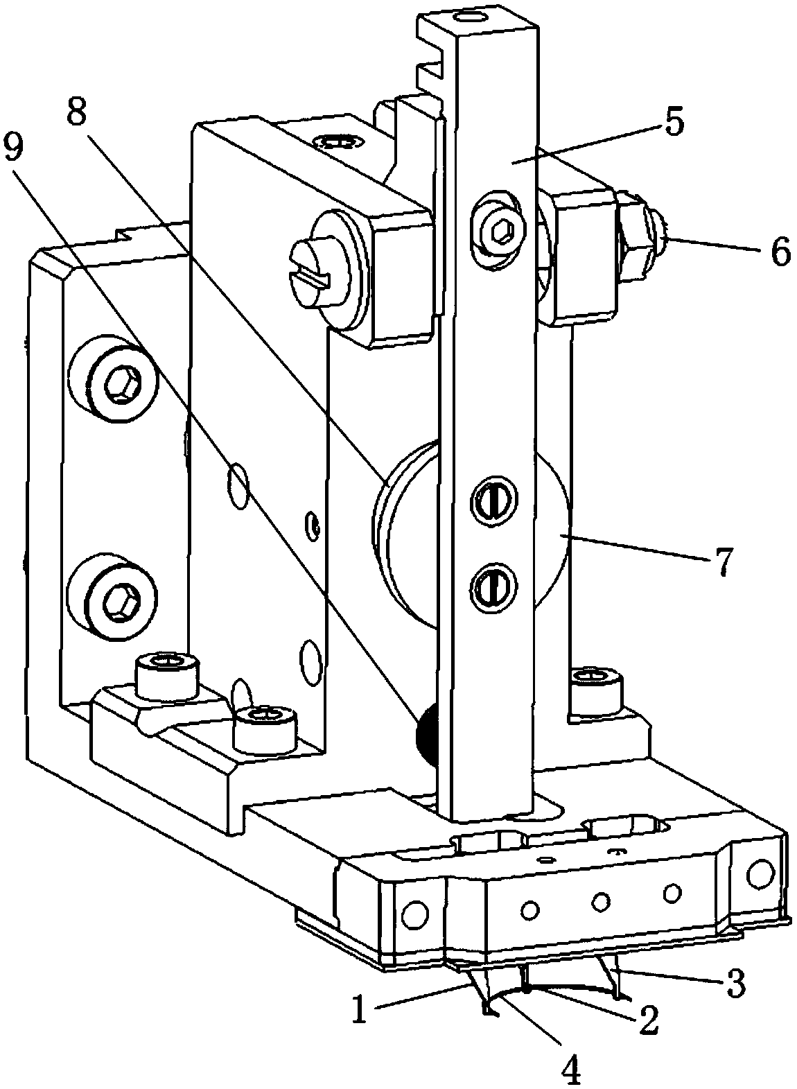
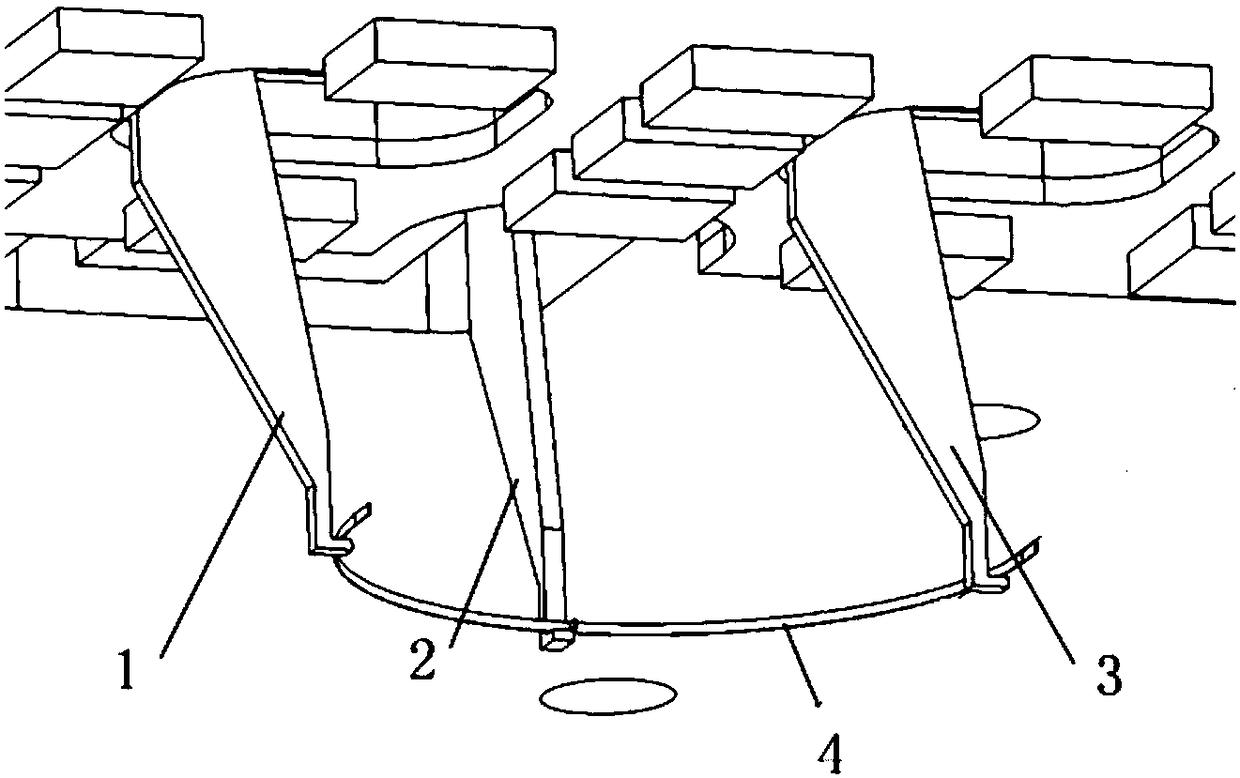
[0020] A device for the stress-free operation of a conductive hairspring, such as figure 1 As shown, it includes the operation substrate, the left claw hook 1, the middle claw hook 2, the right claw hook 3, the conductive balance spring 4 and the moving mechanism. The two L-shaped claws are on the same plane, the left claw 1 and the right claw 3 are fixedly connected to the bottom of the operation substrate, and the direction of the two claws is consistent with the insertion direction, and the distance between the left claw 1 and the right claw 3 is the same as that of the hairspring The two ends and the distance between the two grooves match; the middle claw hook 2 is fixedly connected to the bottom of the moving mechanism, and can move forward and backward with the moving mechanism.

[0021] The electromagnet seat is fixedly connected to the operation base plate, th...


PUM


Abstract

The invention discloses an electric conduction hairspring stress-free operating device. The electric conduction hairspring stress-free operating device comprises an operating basal plate, a left clawhook, a middle claw hook, a right claw hook, an electric conduction hairspring and a moving mechanism, wherein the bottommost end of the left claw hook, the bottommost end of the middle claw hook andthe bottommost end of the right claw hook are L-shaped, the three L-shaped claw hooks are arranged on the same plane, and the left claw hook and the right claw hook are fixedly connected to the bottomof the operating basal plate, the directions of the two claw hooks are consistent with the inserting direction, the spacing between the left claw hook and the right claw hook is matched with that between two end points of the electric conduction hairspring; and the middle claw hook is fixedly connected to the bottom of the moving mechanism, and can moves forward and rearward along with the movingmechanism. When the three-claw mechanism operates the electric conduction hairspring, the electric conduction hairspring is only pressed by upward lifting force which is substantially perpendicular to the direction of the plant, and is free from any component force in the direction in parallel to the plane, so that no elastic deformation can be caused, the electric conduction hairspring can always maintain the original shape, stress-free operation on the electric conduction hairspring is realized, and the conditions that internal stress is generated and interfering torque is caused for instruments are avoided.

Description

technical field [0001] The invention relates to a stress-free operating device for a conductive hairspring, which belongs to the field of instrument assembly. Background technique [0002] The conductive hairspring is a special wire in the inertial instrument. Its function is to realize the electrical connection between the fixed part and the movable part, and provide power input and signal output for the internal movable part. In addition to the function of transmitting current, the conductive hairspring is also required to be designed to be thin and soft in order to minimize the interference torque to internal moving parts. When assembling, the two ends of the conductive hairspring are respectively installed and welded and fixed on the two terminals of the two parts (fixed part and movable part). [0003] At present, the assembly and welding of the conductive hairspring are all done manually. Because of its extremely small size, skilled personnel can only use tweezers un...

Claims


Application Information

Patent Timeline
Patent Type & Authority Applications(China)
IPC IPC(8): B23P19/04B25J15/00H01R43/02
CPCB23P19/04B25J15/0033H01R43/02
Inventor 段荣刘宇轩于得涛余正海董清宇胡玉龙
Owner BEIJING INST OF AEROSPACE CONTROL DEVICES
Learn More