
Spherical piezoelectric stator type gyroscope

A technology of electric stator and gyroscope, applied in the direction of rotating gyroscope, etc., can solve the problems of complex system, harsh processing requirements, and difficulty in miniaturization, and achieve the effect of simplifying the overall structure, avoiding interference torque, and being easy to miniaturize.

Inactive Publication Date: 2012-12-12
NANJING UNIV OF AERONAUTICS & ASTRONAUTICS
View PDF6 Cites 0 Cited by
  • Summary
  • Abstract
  • Description
  • Claims
  • Application Information

AI Technical Summary

Problems solved by technology

Due to the mechanism of electrostatic gyroscopes and magnetic levitation gyroscopes, the price of high precision brings stringent requirements and high costs for manufacturing and processing, and even encounters insurmountable technical bottlenecks when further improving the accuracy. The system is extremely complex and difficult to miniaturize , so that it has not been widely used in the field

Method used


Image

  • Spherical piezoelectric stator type gyroscope
  • Spherical piezoelectric stator type gyroscope
  • Spherical piezoelectric stator type gyroscope

Examples


Embodiment Construction

[0019] The structure and working principle of the present invention will be described in detail below with reference to the drawings and specific embodiments.

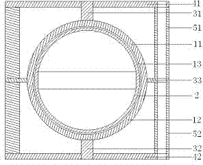
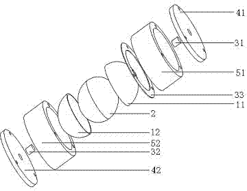
[0020] Such as figure 2 As shown, the present invention provides a spherical piezoelectric stator type gyroscope, including a spherical stator, a spherical rotor and a clamping device, which will be introduced separately below.

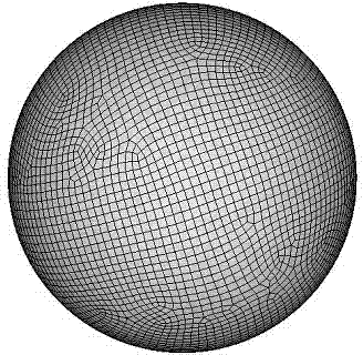
[0021] The spherical stator is directly prepared by piezoelectric material. In this embodiment, for the convenience of installation, the spherical stator is assembled by the first hemispherical piezoelectric stator 11 and the second hemispherical piezoelectric stator 12 by buckling and sealing. An accommodating cavity 13 is formed between the two. The first and second hemispherical piezoelectric stators 11, 12 have the same shape, and both are completely silver-plated on the inner spherical surface, while the outer spherical surface is divided into zones. The divisions can be divided into equal p...


PUM


Abstract

The invention discloses a spherical piezoelectric stator type gyroscope, which comprises a spherical stator, a spherical rotor and a clamping device, wherein the spherical stator is formed by fastening a first hemispherical piezoelectric stator and a second hemispherical piezoelectric stator and assembling in a sealing way, and an accommodating cavity is formed between the first and second hemispherical piezoelectric stators; inner spherical surfaces of the two hemispherical piezoelectric stators are plated with silver electrodes, and the outer spherical surfaces of the two hemispherical piezoelectric stators are plated with the silver electrodes by partitions in the same form; the spherical rotor is positioned in the accommodating cavity of the spherical stator; the clamping device comprises a first axial clamping device and a second axial clamping device which are fixed at two ends of a polar axis of the spherical stator respectively, and a radical clamping device fixed on an equatorial plane of the spherical stator; a sinusoidal voltage signal with a phase difference of phi / 2 is applied to odd partitions and even partitions of the first hemispherical piezoelectric stator respectively, so that a first travelling wave is excited; the second hemispherical piezoelectric stator is powered up in the same way as the first hemispherical piezoelectric stator, so that a second travelling wave is excited; and the spherical rotator rotates in a suspended way under the action of the first and second travelling waves. The gyroscope has simple structure and high precision.

Description

Technical field [0001] The invention belongs to the field of suspended mechanical gyroscopes, and particularly relates to an attitude sensitive gyroscope. Background technique [0002] Gyroscope is a kind of angular motion detection device that uses the moment of momentum sensitive shell of a high-speed rotating body to rotate one or two axes orthogonal to the rotation axis relative to the inertial space. It mainly includes a gyro rotor, an inner and outer frame and accessories (referring to torque motors, Signal sensor, etc.). [0003] The non-contact support system can effectively reduce the interference torque and improve the accuracy of the gyro system. Due to the mechanism of electrostatic gyroscopes and magnetic levitation gyroscopes, the cost of high precision brings demanding manufacturing and processing requirements and high costs, and even further improvement of accuracy encounters insurmountable technical bottlenecks. The system is extremely complex and difficult to m...

Claims


Application Information

Patent Timeline
Patent Type & Authority Patents(China)
IPC IPC(8): G01C19/02
Inventor 陈超李繁贾兵
Owner NANJING UNIV OF AERONAUTICS & ASTRONAUTICS
Learn More