Vacuum pneumatic lock die

A mold-locking and vacuum technology, applied in the field of vacuum pneumatic mold-locking, can solve the problems of simple structure, poor use effect, low precision, etc.

Inactive Publication Date: 2018-09-14
SUZHOU JIEHE IND
View PDF3 Cites 0 Cited by
  • Summary
  • Abstract
  • Description
  • Claims
  • Application Information

AI Technical Summary

Problems solved by technology

The die-drawing mechanism used in the prior art has a simple structure, cannot quickly and effec...

Method used


Image

  • Vacuum pneumatic lock die
  • Vacuum pneumatic lock die

Examples


Embodiment Construction

[0012] The preferred embodiments of the present invention are described in detail below, so that the advantages and features of the present invention can be more easily understood by those skilled in the art, so as to define the protection scope of the present invention more clearly.

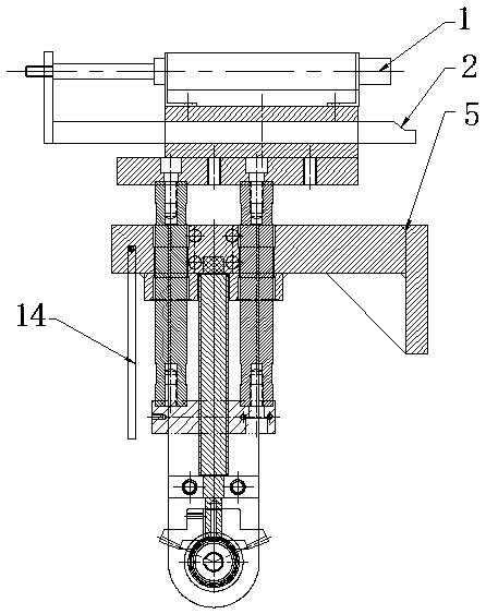
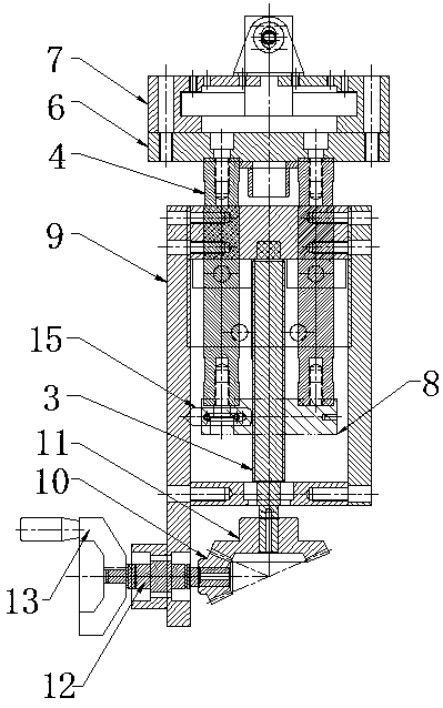
[0013] Described in the present invention is a kind of vacuum pneumatic mold clamping, such as figure 1 combine figure 2 As shown, it includes a cylinder 1, a drawing plate 2, a screw mandrel 3, a guide post 4 and a mounting plate 5, the screw 3 is longitudinally arranged below the mounting plate 5, and the guide post 4 is longitudinally arranged on the mounting plate 5, so The upper end of the guide post 4 is set above the mounting plate 5 and is provided with an upper fixing plate 6 of the guide post. The drawing formwork 2 is arranged above the upper fixing plate 6 of the guide post through the drawing guide rail 7, and the cylinder 1 is correspondingly arranged on the drawing board. The to...


PUM


Abstract

The invention discloses a vacuum pneumatic lock die. The vacuum pneumatic lock die comprises an air cylinder, a die drawing plate, a lead screw, a guide column and an installing plate. The lead screwis longitudinally arranged below the installing plate. The guide column is longitudinally arranged on the installing plate. The upper end portion of the guide column is arranged above the installing plate and provided with a guide column upper fixing plate. The die drawing plate is arranged above the guide column upper fixing plate through a die drawing guide rail. The air cylinder is correspondingly arranged above the die drawing guide rail and correspondingly connected with the die drawing plate. A guide column lower fixing plate is arranged at the lower end portion of the guide column, thelead screw is in threaded connection with the guide column lower fixing plate, and one side of the installing plate is further longitudinally provided with a gear fixing plate. A driving bevel gear iscorrespondingly arranged below the gear fixing plate. A driven bevel gear is correspondingly arranged below the lead screw to be correspondingly connected with the driving bevel gear. The vacuum pneumatic lock die is simple and reasonable in structure, convenient to use and capable of rapidly finishing lifting adjustment, and gear transmission precision is high.

Description

technical field [0001] The invention relates to a vacuum pneumatic mold clamping. Background technique [0002] When the mold is opened, the adhesive force generated during the vulcanization process of the rubber makes the mold stick together and cannot be separated normally. The drawing plate of the clamping structure is inserted into the mold, and when the mold is lowered, the mold that needs to be separated is pulled down to complete the separation. The die-drawing mechanism adopted in the prior art has a simple structure, cannot quickly and effectively complete the positioning of the die-locking mechanism, has low precision, and is not effective in use. Contents of the invention [0003] The purpose of the present invention is to provide a vacuum pneumatic mold clamping with simple and reasonable structure, easy to use, fast lifting adjustment and high gear transmission precision. [0004] The technical solution of the present invention is a vacuum pneumatic mold clam...

Claims


Application Information

Patent Timeline
IPC IPC(8): B29C45/64
CPCB29C45/64
Inventor 齐超
Owner SUZHOU JIEHE IND
Why Eureka
Try Eureka