A printing ink drying device
A drying device and drying device technology are applied in printing, general parts of printing machinery, printing presses, etc., which can solve the problems of easy smearing of ink and taking a long time, and achieve the effect of improving efficiency
- Summary
- Abstract
- Description
- Claims
- Application Information
AI Technical Summary
Problems solved by technology
Method used
Image

Examples
Embodiment 1
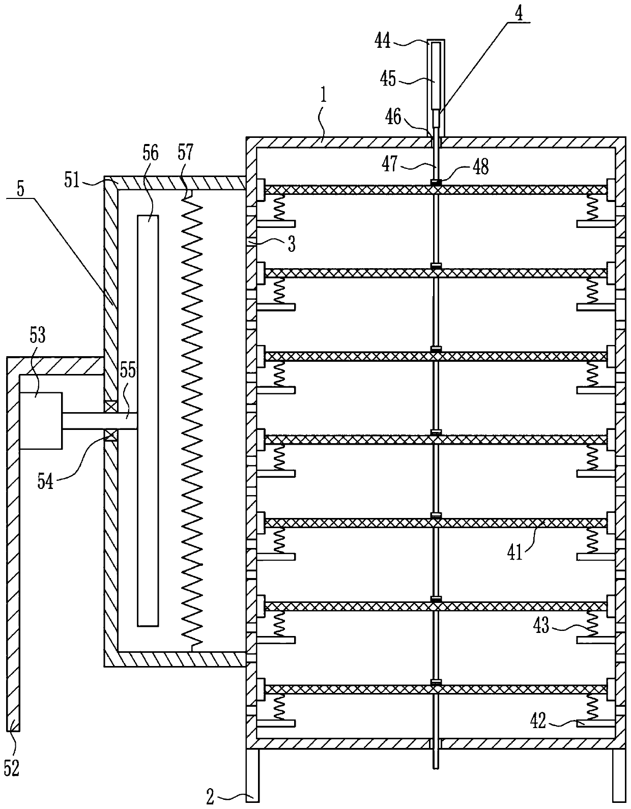
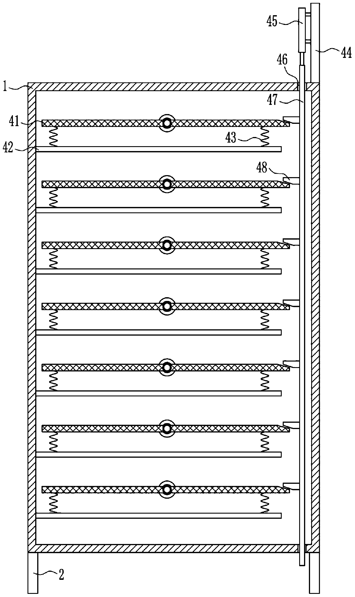
[0032] A printing ink drying device, such as Figure 1-8 As shown, it includes a box body 1, legs 2, a swing device 4 and a drying device 5. The four corners of the bottom of the box body 1 are equipped with outriggers 2, and the left and right sides of the box body 1 are evenly spaced with small holes 3. , The box body 1 is provided with a swing device 4, and the box body 1 is provided with a drying device 5 on the left side.
Embodiment 2
[0034] A printing ink drying device, such as Figure 1-8 As shown, it includes a box body 1, legs 2, a swing device 4 and a drying device 5. The four corners of the bottom of the box body 1 are equipped with outriggers 2, and the left and right sides of the box body 1 are evenly spaced with small holes 3. , The box body 1 is provided with a swing device 4, and the box body 1 is provided with a drying device 5 on the left side.
[0035]Swing device 4 comprises net plate 41, horizontal plate 42, the first spring 43, mounting plate 44, cylinder 45, guide rod 47 and contact block 48, and the rotating type that is evenly spaced in the casing 1 is equipped with net plate 41, each Horizontal plates 42 are installed on the left and right sides below the screen plate 41, and the aperture 3 is located between every two horizontal plates 42, and the front and rear sides of each horizontal plate 42 top are connected with the bottom of the screen plate 41 with a first spring 43. A mountin...
Embodiment 3
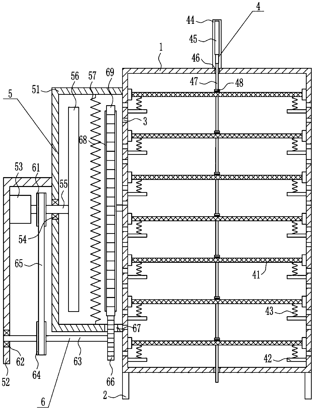
[0037] A printing ink drying device, such as Figure 1-8 As shown, it includes a box body 1, legs 2, a swing device 4 and a drying device 5. Outriggers 2 are installed at the four corners of the bottom of the box body 1, and small holes 3 are evenly spaced on the left and right sides of the box body 1. , The box body 1 is provided with a swing device 4, and the box body 1 is provided with a drying device 5 on the left side.
[0038] Swing device 4 comprises net plate 41, horizontal plate 42, the first spring 43, mounting plate 44, cylinder 45, guide rod 47 and contact block 48, and the rotating type that is evenly spaced in the casing 1 is equipped with net plate 41, each Horizontal plates 42 are installed on the left and right sides below the screen plate 41, and the aperture 3 is located between every two horizontal plates 42, and the front and rear sides of each horizontal plate 42 top are connected with the bottom of the screen plate 41 with a first spring 43. A mounting ...
PUM
 Abstract
Description
Claims
Application Information
 - R&D
- Intellectual Property
- Life Sciences
- Materials
- Tech Scout
- Unparalleled Data Quality
- Higher Quality Content
- 60% Fewer Hallucinations
Browse by: Latest US Patents, China's latest patents, Technical Efficacy Thesaurus, Application Domain, Technology Topic, Popular Technical Reports.
© 2025 PatSnap. All rights reserved.Legal|Privacy policy|Modern Slavery Act Transparency Statement|Sitemap|About US| Contact US: help@patsnap.com