Carrying equipment for moving skid helicopter on ground
A technology for handling equipment and helicopters, applied in the field of general aviation, can solve the problems that the safe, stable, convenient and efficient transfer of the helicopter cannot be guaranteed, the installation process of parts and components is time-consuming and laborious, and the operation steps of the helicopter are cumbersome. The effect of reducing material usage, ensuring joint strength and sliding stability
- Summary
- Abstract
- Description
- Claims
- Application Information
AI Technical Summary
Problems solved by technology
Method used
Image
Examples
Embodiment 1
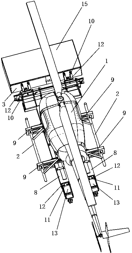
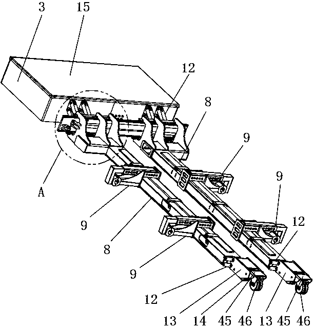
[0047] Such as Figures 1 to 8 Shown, a kind of handling equipment that is used for the ground movement of sled type helicopter, comprises head mechanism and vehicle frame mechanism; The control system module 7, the battery 4 supplies power to the motor drive wheel 5, the hydraulic system 6 and the control system module 7, and the battery 4, the motor drive wheel 5 and the hydraulic system 6 are all connected to the control system module 7; the frame mechanism includes a beam 8, A clamping structure 9 is installed on the crossbeam 8, and the clamping structure 9 is used for clamping the sledge stand 2 of the helicopter 1; The front end is connected with the front hydraulic cylinder 10 through the linkage mechanism 12, and the two can jointly control the vertical movement of the beam 8 relative to the cabin 3; the rear end of the beam 8 is connected with the rear support frame through the linkage mechanism 12 and the rear hydraulic cylinder 11 13. The two can jointly control t...
Embodiment 2
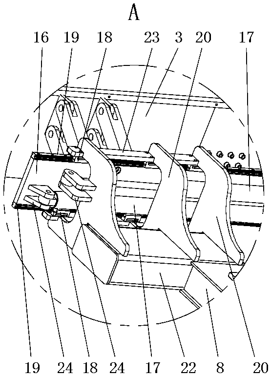
[0052] Such as image 3 and 7 As shown, on the basis of Embodiment 1, the sliding seat 18 is installed on the upper end and the lower end of the beam 8 through the connecting seat 20, the connecting seat 20 is fixedly installed on the front end of the beam 8, and the front end of the connecting seat 20 is provided with an installation slot 21, and the sliding seat 18 are respectively installed on the inner side of the upper end and the inner side of the lower end of the installation slot 21; the left and right ends of the rear end surface of the sliding support plate 16 are equipped with a swivel seat 24, and the rear end of the installation slot 21 is also equipped with a swivel seat 24. Two horizontal hydraulic cylinders The bottom ends of the cylinder body of 17 are connected with the two rotating seats 24 correspondingly on the sliding support plate 16 respectively, and the piston rod tops of the two horizontal hydraulic cylinders 17 are respectively connected with the rot...
Embodiment 3
[0055] Such as Figure 12 and 14 As shown, on the basis of Embodiment 2, the clamping structure 9 specifically includes an adjusting hydraulic cylinder 25, a connecting block 26, an adjusting plate 27 and a clamping group, the adjusting hydraulic cylinder 25 is connected with the hydraulic system 6, and the inside of the beam 8 is horizontally An adjustment hydraulic cylinder 25 is fixedly installed, and the top end of the piston rod of the adjustment hydraulic cylinder 25 is fixedly connected with the connection block 26. The adjustment plate 27 is arranged along the length direction of the beam 8 and is located above the beam 8. The connection block 26 is fixedly connected with the bottom end of the adjustment plate 27 , the adjustment hydraulic cylinder 25 can control the adjustment plate 27 to move left and right, the upper end surface of the beam 8 is equipped with a limit guide bead 32, the left and right ends of the limit guide bead 32 are fixed in contact with the uppe...
PUM
 Abstract
Description
Claims
Application Information
 - R&D
- Intellectual Property
- Life Sciences
- Materials
- Tech Scout
- Unparalleled Data Quality
- Higher Quality Content
- 60% Fewer Hallucinations
Browse by: Latest US Patents, China's latest patents, Technical Efficacy Thesaurus, Application Domain, Technology Topic, Popular Technical Reports.
© 2025 PatSnap. All rights reserved.Legal|Privacy policy|Modern Slavery Act Transparency Statement|Sitemap|About US| Contact US: help@patsnap.com


