Conveying device

A technology for conveying devices and conveyor belts, which is applied in the direction of conveyors, conveyor objects, mechanical conveyors, etc. It can solve the problems of wheel hub pushing deviation, affecting the normal operation of detection work, and inability to adjust the position, so as to achieve accurate lateral adjustment and prevent The effect of deviation and convenient adjustment

Pending Publication Date: 2018-09-14
苏州优纳科技有限公司 +2
View PDF9 Cites 8 Cited by
  • Summary
  • Abstract
  • Description
  • Claims
  • Application Information

AI Technical Summary

Problems solved by technology

[0006] Therefore, the technical problem to be solved by the present invention is to overcome the position adjustment of the wheel hub located on the conveying device by the rough positioning device in the prior art. Push deviation, and then affect the technical defect of the normal detection work, so as to provide a way to gradually adjust the lateral position of the hub perpendicular to the conveying direction during the conveying process, so there is no need to judge the start time, and the conveying that will not push the hub device

Method used


Image

  • Conveying device
  • Conveying device
  • Conveying device

Examples


Embodiment 1

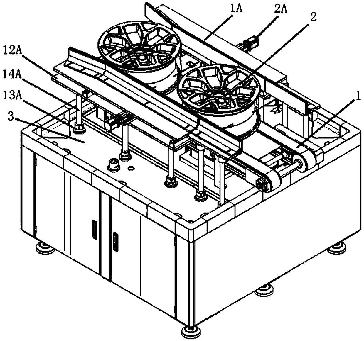
[0066] This embodiment provides a delivery device, such as figure 1 , Figure 4 As shown, it includes a conveying track 1, an adjustment structure and a mounting plate 12A.

[0067] The conveying track 1 has a conveying surface for conveying objects, and the object is a wheel hub 2 , and the conveying surface of the conveying track 1 is suitable for carrying the wheel hub 2 .

[0068] The adjustment structure is installed on the installation plate 12A, and the installation plate 12A is fixedly installed on the base 3 through the vertical adjustment structure.

[0069] The vertical adjustment structure includes a connecting base 13A and a column 14A, and the connecting bases 13A are fixed on the mounting plate 12A and the base 3 oppositely in pairs, and the connecting bases 13A opposite in pairs are The upright post 14A is supported therebetween, and the upright post 14A is inserted into the connection seat 13A and connected with the connection seat 13A in a tight manner.

...


PUM


Abstract

The invention provides a conveying device, and belongs to the technical field of automobile detection equipment. The conveying device comprises a conveying rail and adjusting structures, wherein the conveying rail is provided with a conveying surface used for conveying objects, and the adjusting structures are arranged on the two transverse sides of the conveying rail to form an adjusting channel;and in the process of conveying the objects on the conveying rail, the objects entering the adjusting channel are subjected to transverse adjustment one by one. According to the conveying device, theadjusting structures are arranged on the two transverse sides of the conveying rail, and can be used for transversely adjusting the objects conveyed on the conveying rail in the conveying process, and the adjusting structures are capable of preventing the objects from being blocked when the objects are being transversely adjusted; according to the conveying device, the position of each object does not need to be accurately detected when the position of the object is transversely adjusted, and the time to start the adjusting structures does not need to be judged, so that the whole adjusting process is convenient to adjust, the error rate is low, a wheel hub cannot be pushed slantly, so that the safety is good.

Description

technical field [0001] The invention relates to the technical field of automobile wheel hub detection equipment, in particular to a conveying device capable of laterally limiting a wheel hub to be detected. Background technique [0002] The wheel hub is an important appearance and safety part of the car. During the production process, cracks are prone to occur on the surface. In order to ensure the quality of the factory, the appearance of the wheel hub needs to be inspected. In the prior art, the detection of the appearance of the wheel hub is usually by manual identification, but this method is inefficient and cannot be carried out continuously and stably, and cannot meet the requirements of modern industrial production lines. [0003] Chinese patent document CN106423894A discloses an automatic sorting device for wheel appearance based on machine vision, including a detection section conveying device, a rough positioning device located below the detection section conveying...

Claims


Application Information

Patent Timeline
Patent Type & Authority Applications(China)
IPC IPC(8): B65G35/00B65G47/24
CPCB65G35/00B65G47/24
Inventor 支宏毅郑众喜李鹏杰李亮张振刚李占鑫类衍明刘阳佟尔冰武汉琦陈彦广
Owner 苏州优纳科技有限公司
Why Eureka
Try Eureka