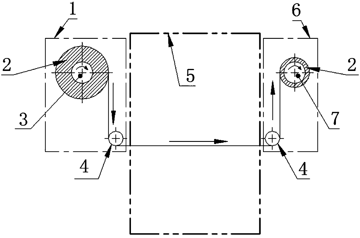
A combined structure with constant resistance and the ability to adjust radial and axial dimensions at the same time
A technology of axial size and combined structure, applied in the direction of transportation and packaging, transportation packaging, packaging, etc., can solve the problems of unstable resistance, inconvenient adjustment, inconvenient maintenance, etc., and achieve the solution of unstable resistance and simple and convenient adjustment methods , the effect of improving production efficiency
- Summary
- Abstract
- Description
- Claims
- Application Information
AI Technical Summary
Problems solved by technology
Method used
Image
Examples
Embodiment 1
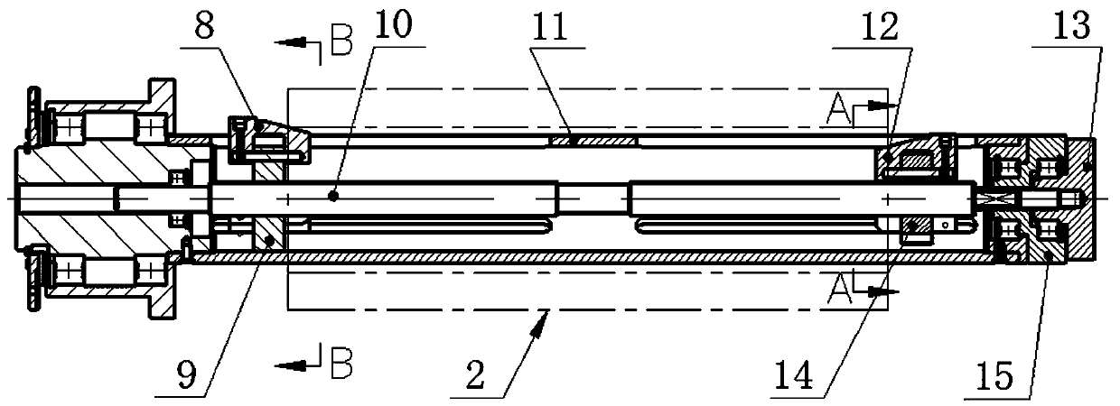
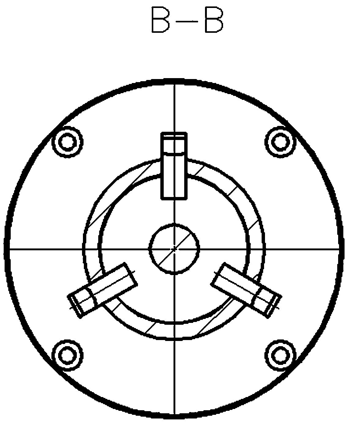
[0050] The present invention designs a combination structure with constant resistance and can adjust radial and axial dimensions at the same time. The adjustment handle for axial adjustment is convenient for the user to quickly and quickly adjust the axial direction during use. It has the advantages of convenient adjustment and less time-consuming, such as Figure 2~8 As shown, the following arrangement structure is adopted in particular: comprising a resistance structure and a coherent shaft structure mutually connected through a two-way screw rod 10, the resistance structure includes a flange head, a damping disc 19 and a magnet 20, and the magnet 20 is arranged on the damping between the disc 19 and the flange head, and both the flange head and the damping disc 19 are sleeved on the two-way screw rod 10; the coherent shaft structure body includes a coating segment and an adjustment segment arranged on the two-way screw rod 10 in sequence; An axial adjustment handle 13 sleev...
Embodiment 2
[0057] This embodiment is further optimized on the basis of the above embodiments, such as Figure 2~8 As shown, further in order to better realize the present invention, the following arrangement structure is particularly adopted: the flange head includes a flange structure 18 and an extension shaft 21, and the extension shaft 21 is sleeved on the two-way screw rod 10, preferably , the extension shaft 21 is integrated with the hollow shaft 11 through an interference fit, and a rolling bearing (second rolling bearing 17) is fitted between the extension shaft 21 of the nearly coherent shaft structure section and the two-way screw 10; the flange The structure 18 is also fitted on the extension shaft 21 through a rolling bearing (the second rolling bearing 17 ); the damping disc 19 is fitted on the far coherent shaft structure end of the flange structure 18 through a magnet 20 .
[0058] A damping disc 19 is added at the end of the extension shaft 21, and the extension shaft 21 a...
Embodiment 3
[0060] This embodiment is further optimized on the basis of any of the above embodiments, such as Figure 2~8 As shown, further in order to better realize the present invention, the following arrangement structure is adopted in particular: a radial adjustment handle 15 sleeved on the two-way screw rod 10 is also provided on the adjustment section, and the diameter of the upper diameter of the adjustment section is The adjustment handle 15 is placed inside the axial adjustment handle 13, and the axial adjustment handle 13 is placed at the end of the two-way screw rod 10. Between the radial adjustment handle 15 and the axial adjustment handle 13, a rolling bearing (the first rolling bearing 16).
[0061] When setting, the adjustment section on the two-way screw mandrel 10 is also provided with a radial adjustment handle 15, so that the radial adjustment handle 15 can carry out radial adjustment size. When setting, the radial adjustment handle 15 is arranged inside, and A matchi...
PUM
 Abstract
Description
Claims
Application Information
 - R&D
- Intellectual Property
- Life Sciences
- Materials
- Tech Scout
- Unparalleled Data Quality
- Higher Quality Content
- 60% Fewer Hallucinations
Browse by: Latest US Patents, China's latest patents, Technical Efficacy Thesaurus, Application Domain, Technology Topic, Popular Technical Reports.
© 2025 PatSnap. All rights reserved.Legal|Privacy policy|Modern Slavery Act Transparency Statement|Sitemap|About US| Contact US: help@patsnap.com


