Spinning machine

A technology of mechanical and movable connection, applied in the field of spinning machinery, can solve the problems of reducing work quality and inability to remove iron impurities, and achieve the effect of improving work quality

Inactive Publication Date: 2018-09-14
王振兴
View PDF2 Cites 6 Cited by
  • Summary
  • Abstract
  • Description
  • Claims
  • Application Information

AI Technical Summary

Problems solved by technology

[0004] Aiming at the deficiencies in the prior art, the purpose of the present invention is to provide a spinning machine to solve the problem that the iron impurities in the cotton cannot be removed and the working quality is reduced.

Method used


Image

  • Spinning machine
  • Spinning machine

Examples


Embodiment Construction

[0017] In order to make the technical means, creative features, goals and effects achieved by the present invention easy to understand, the present invention will be further described below in conjunction with specific embodiments.

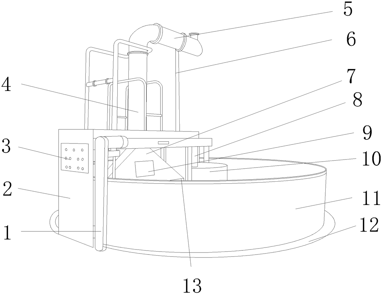
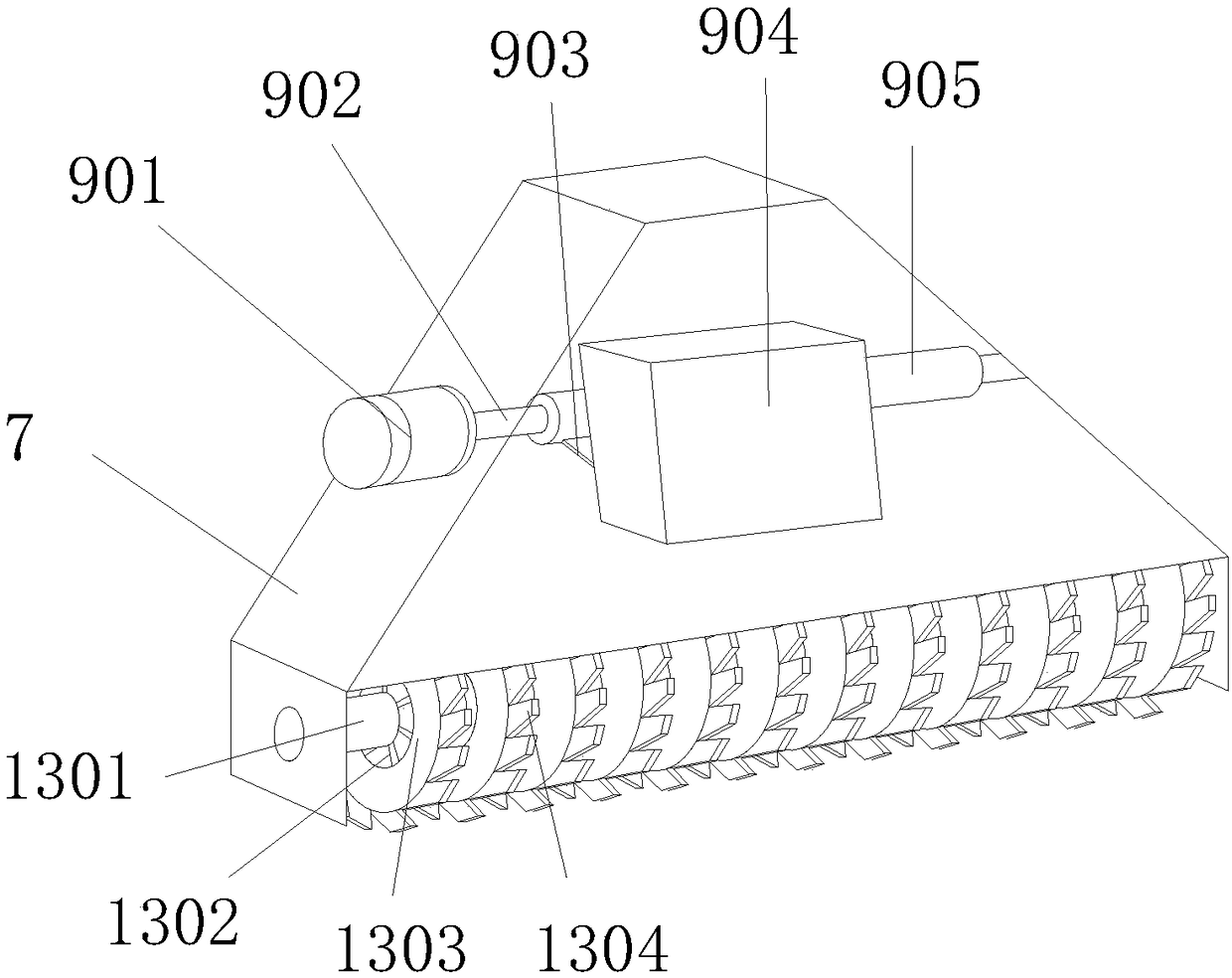
[0018] see figure 1 , figure 2 , the present invention provides a spinning machine technical solution: its structure includes a photoelectric tube 1, a bracket 2, a control panel 3, a telescopic tube 4, a cotton delivery tube 5, a screw 6, a trolley 7, a central shaft 8, an iron absorbing device 9, Inner ring wallboard 10, outer ring wallboard 11, ground rail 12, cotton catcher 13, described outer ring wallboard 11 is connected with ground rail 12, and described ground rail 12 is movably connected with support 2, and described support 2 A control panel 3 is provided, the control panel 3 is connected with the photoelectric cell 1, the support 2 is connected with the telescopic tube 4, the bottom of the telescopic tube 4 is connected with the trol...


PUM


Abstract

The invention discloses a spinning machine. The spinning machine structurally comprises a phototube, a support, a control panel, a telescopic tube, a cotton delivery tube, a screw, a cart, a central shaft, an iron attracting device, inner-circle wall boards, outer-circle wall boards, a ground rail and a cotton grabbing beater, wherein the outer-circle wall boards are connected with the ground rail, the ground rail is movably connected with the support, the support is provided with the control panel, the control panel is connected with the phototube, the support is connected with the telescopictube, the bottom of the telescopic tube is connected with the cart, the iron attracting device is arranged in the cart, the bottom of the cart is movably connected with the cotton grabbing beater, the top of the telescopic tube is connected with the cotton delivery tube, the support is movably connected with the central shaft, the central shaft is movably connected with the inner-circle wall boards, the iron attracting device consists of a motor, a rotary shaft, an iron scraping plate, an iron collecting box and a powerful magnet, the motor is movably connected with the rotary shaft, the rotary shaft is connected with the powerful magnet, and the powerful magnet is movably connected with the iron scraping plate. The spinning machine can attract irony impurities in cotton, play an impurityremoving effect and improve the working quality.

Description

technical field [0001] The invention is a spinning machine, which belongs to the field of spinning machines. Background technique [0002] There are many kinds of spinning machines, and the machine structures, uses and performances are different. [0003] The prior art discloses that the application number is: 201420193832.5, which discloses a cotton catching machine, including a cotton catching device, a transmission device and a cotton storage bin, and the transmission device includes a beam, a power source and a central column, and the central column is fixed On the base, the power source is set inside the center column, and the power source drives the beam to move. One end of the beam is connected to the center column, and the other end is movable on the outer wall column of the cotton storage bin. The cotton catching device includes Suction hood, cotton catcher and cotton delivery pipe, the top of the suction hood is connected to the cotton delivery pipe, the inner bot...

Claims


Application Information

Patent Timeline
Patent Type & Authority Applications(China)
IPC IPC(8): D01G7/02D01G7/06
CPCD01G7/02D01G7/06
Inventor 王振兴
Owner 王振兴
Why Eureka
Try Eureka