Rotary lifting parking device and operation method thereof

A parking device, rotary lift technology, applied to the building, building type, building and other directions where cars are parked, can solve the problems of complex mechanical structure, wire rope breaking, large initial torque, etc., to ensure the overall structural strength and convenient parking. and driving out, ensuring the effect of structural strength

Pending Publication Date: 2018-09-14
HUBEI THREE GORGES POLYTECHNIC
View PDF3 Cites 9 Cited by
  • Summary
  • Abstract
  • Description
  • Claims
  • Application Information

AI Technical Summary

Problems solved by technology

However, the mechanical structure of this parking device is relatively complicated, and its stability cannot be well guaranteed during use, and there are difficulties in the actual promotion process.
[0006] In CN 104164989 A, a swinging arm sliding combined three-dimensional garage is disclosed. This three-dimensional garage combines a parallelogram lifting mechanism and a track mechanism to realize vertical parking. Medium, the initial torque is large, and the wire rope is easily broken

Method used


Image

  • Rotary lifting parking device and operation method thereof
  • Rotary lifting parking device and operation method thereof
  • Rotary lifting parking device and operation method thereof

Examples


Embodiment 1

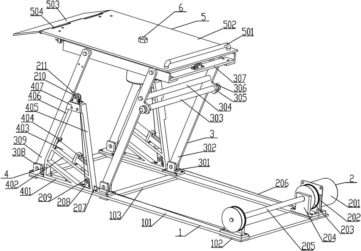
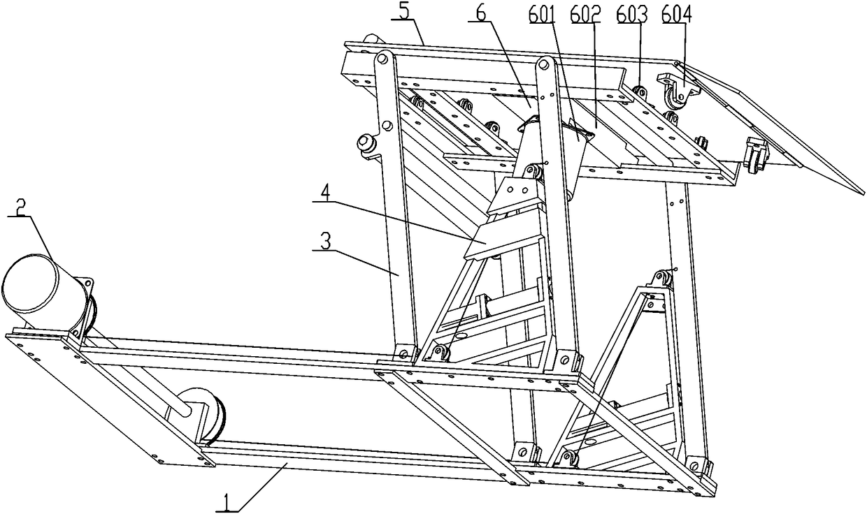
[0067] like Figure 1-3 Among them, the rotary lifting parking device, which includes a fixed base assembly 1 for supporting the entire device, one end of the fixed base assembly 1 is installed with a swing rod lifting mechanism 3 for lifting, and the top of the swing rod lifting mechanism 3 is supported and installed There is a rotatable parking pallet device 5, and the position where the parking pallet device 5 is connected to the fork lifting mechanism 3 is equipped with a rotary power device 6 for driving the parking pallet device 5 to rotate, and the fork lifting mechanism 3 A triangular support mechanism 4 for supporting it is installed between the two swing rods, the triangular support mechanism 4 is fixedly installed on the fixed base assembly 1, and the swing rod lifting mechanism 3 is connected with the hoisting mechanism for driving its lifting 2 connected. By adopting the above-mentioned rotary lifting parking device, avoidable double-deck parking can be realized,...

Embodiment 2

[0087] The operation method of any one of the rotary lifting parking devices, it includes the following steps:

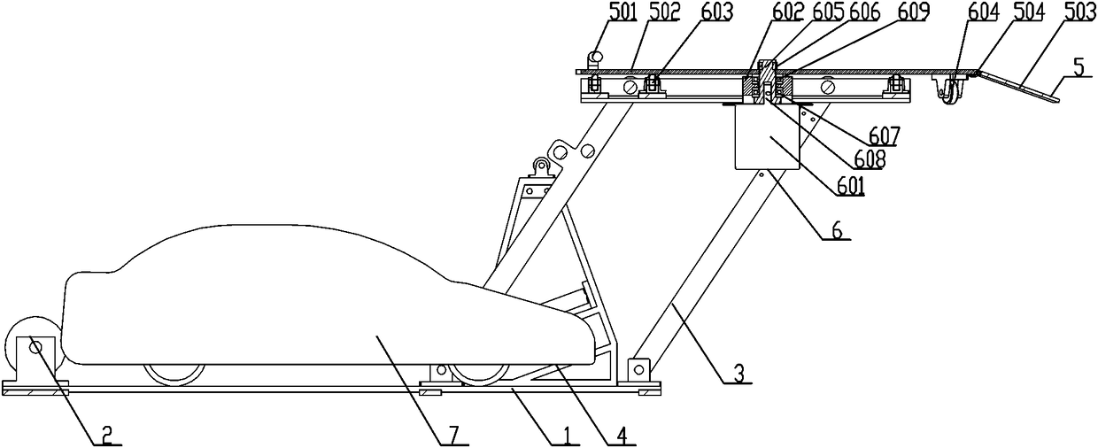
[0088] Such as Figure 4-8 When parking is required:

[0089] Step1: Loosen the wire rope 206 of the hoisting mechanism 2, and then loosen the swing rod lifting mechanism 3, and push the whole swing rod lifting mechanism 3 to rotate through the spring push rod 403. When it is pushed to a certain angle, the swing rod lifting mechanism 3 will move under its own gravity Continue to rotate under the action, finally make the parking pallet device 5 supported on the ground;

[0090] Step2: Start the rotating motor 601 of the rotating power unit 6, drive the parking plate 502 to rotate 90° through the rotating motor 601, and make the slope plate 503 parallel to the direction in which the car travels;

[0091] Step3: Start the car, make it slowly drive to the top of the parking plate 502 through the slope plate 503, and limit the position of the car through the gear lever...


PUM


Abstract

The invention relates to a rotary lifting parking device and an operation method thereof. The rotary lifting parking device comprises a fixed base assembly used for supporting the whole device. A swing rod lifting mechanism used for rising and falling is mounted at one end of the fixed base assembly, and a parking supporting plate device capable of rotating is mounted at the top of the swing rod lifting mechanism in a supporting mode. A rotary power device used for driving the parking supporting plate device to rotate is mounted at the connected position of the parking supporting plate deviceand the swing rod lifting mechanism. A triangular supporting mechanism used for supporting swing rods is mounted between the two swing rods of the swing rod lifting mechanism and fixedly mounted on the fixed base assembly. The swing rod lifting mechanism is connected with a winch mechanism used for driving the swing rod lifting mechanism to rise and fall. The rotary lifting parking device can be placed on the two sides of a road and does not occupy the lane space.

Description

technical field [0001] The invention belongs to the field of mechanical three-dimensional garage devices, in particular to a rotary lifting parking device and an operation method. Background technique [0002] With the improvement of living standards, there are more and more private cars. However, in residential areas without special parking lots, the parking area is too small, and some park on both sides of the road and occupy the driveway. In order to solve this problem, a rotary lifting parking device needs to be designed. [0003] Existing some parking devices on the market at present, as three-dimensional parking garage etc., mostly volume is bigger, is not suitable for being arranged in the living area. Some small parking devices with upper and lower floors, the upper parking space is limited by the lower parking. When in use, the car parked on the lower floor must be moved out so that the car on the upper floor can come down, which is very inconvenient. [0004] A...

Claims


Application Information

Patent Timeline
Patent Type & Authority Applications(China)
IPC IPC(8): E04H6/06
CPCE04H6/06
Inventor 兰杰刘华华许颖王伟奇方瑛冉磊郑力铭蔡厚澍陈俊李鑫浩
Owner HUBEI THREE GORGES POLYTECHNIC
Why Eureka
Try Eureka