
Casing annulus pressure simulating device

A casing annulus and simulation device technology, applied in the directions of measurement, wellbore/well components, earthwork drilling and production, etc., can solve the problems of not meeting the needs of wellhead safety assessment, inaccurate casing annulus pressure, etc., to improve production Safety and efficiency, the effect of reducing production accidents

Pending Publication Date: 2018-09-14
CHINA UNIV OF PETROLEUM (BEIJING)
View PDF9 Cites 2 Cited by
  • Summary
  • Abstract
  • Description
  • Claims
  • Application Information

AI Technical Summary

Problems solved by technology

[0005] The invention provides a casing annular pressure simulation device to solve the technical problem that the existing theoretical calculation of the casing annular pressure is inaccurate and cannot meet the needs of wellhead safety assessment

Method used


Image

  • Casing annulus pressure simulating device
  • Casing annulus pressure simulating device
  • Casing annulus pressure simulating device

Examples


Embodiment Construction

[0031] Embodiments of the present invention are described in detail below, examples of which are shown in the drawings, wherein the same or similar reference numerals designate the same or similar elements or elements having the same or similar functions throughout. The embodiments described below by referring to the figures are exemplary and are intended to explain the present invention and should not be construed as limiting the present invention.

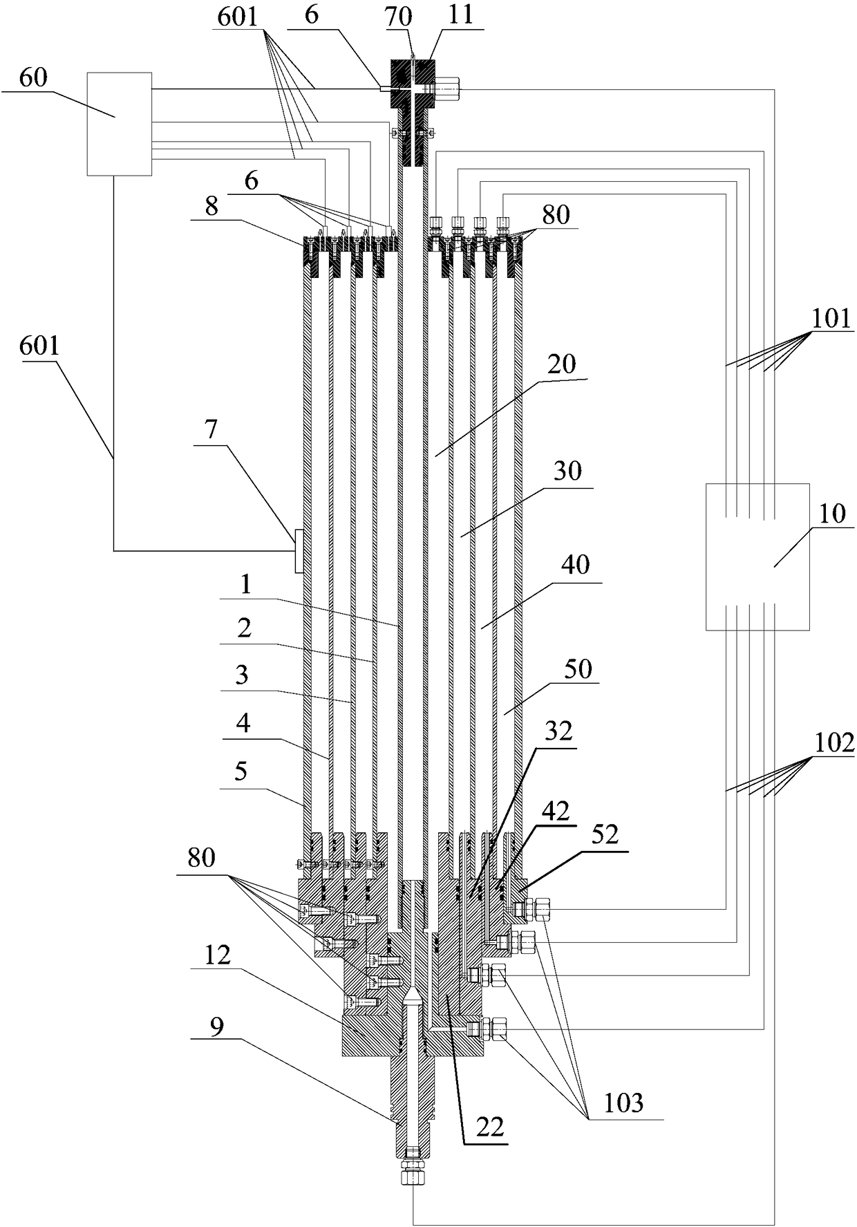
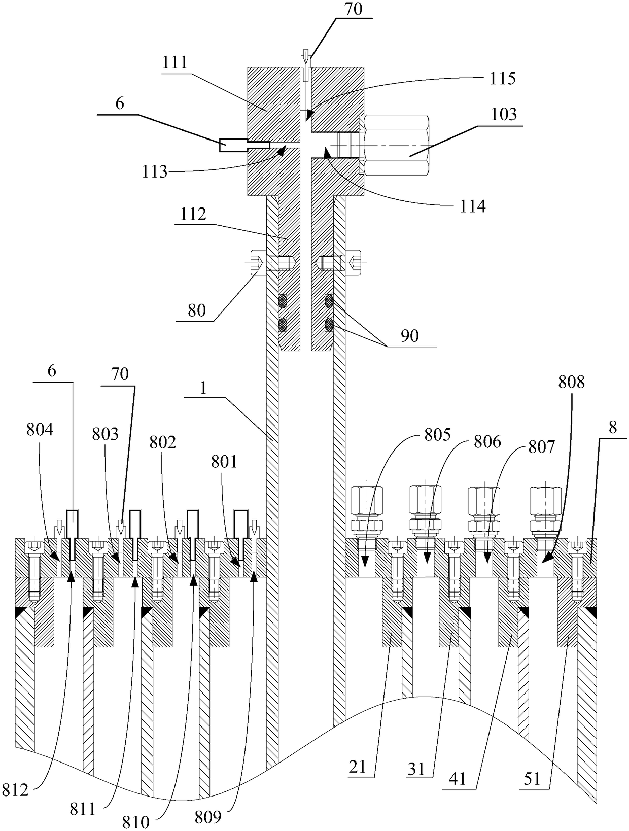
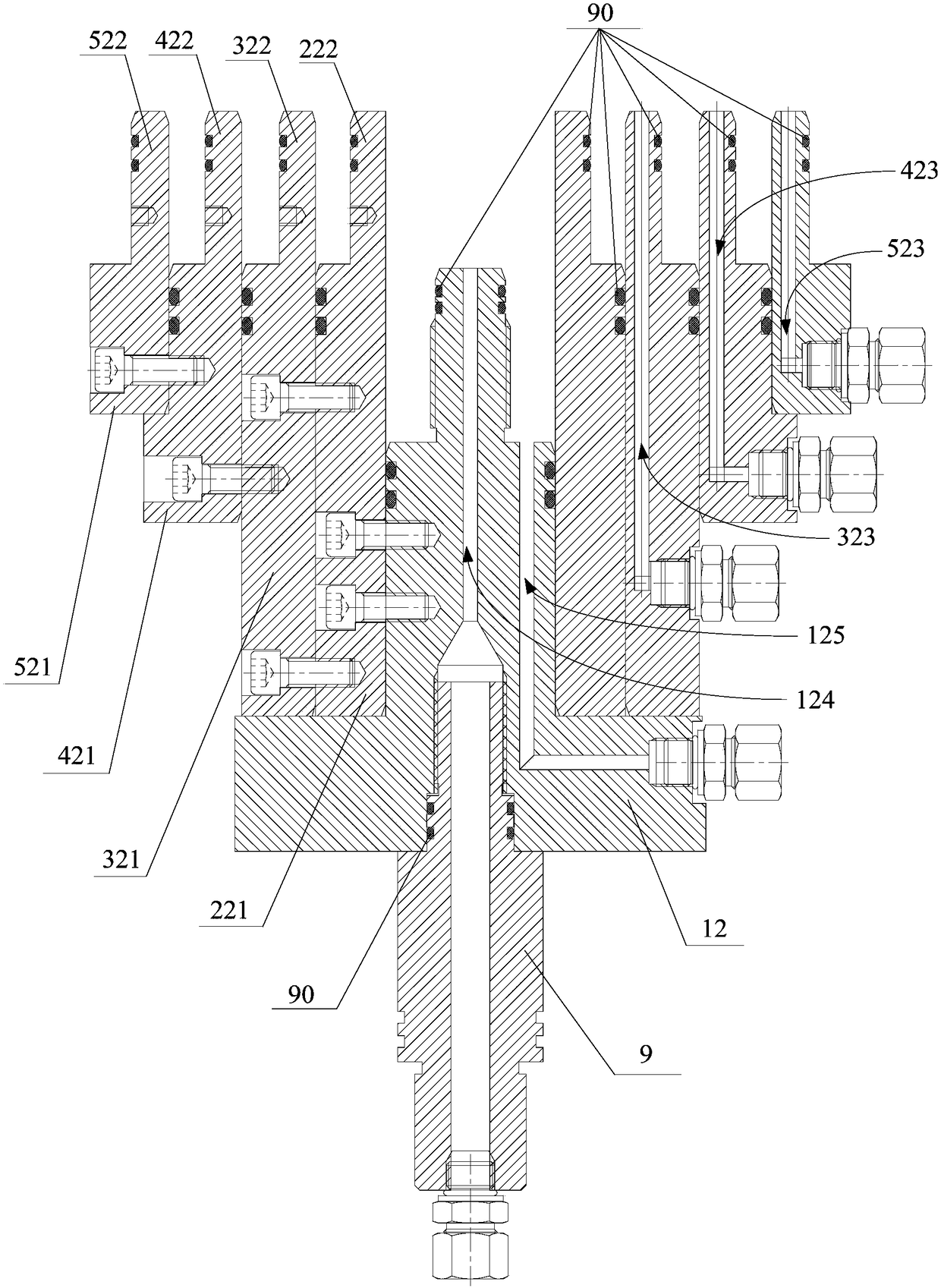
[0032] figure 1 It is a structural schematic diagram of the casing annular pressure simulation device of the present invention; figure 2 for figure 1 The enlarged schematic diagram of the part of the first sealing device in ; image 3 for figure 1Schematic diagram of the structure of the second sealing device; Figure 4 for image 3 Schematic diagram of the structure of the medium oil pipe seat.

[0033] refer to Figure 1 to Figure 4 , this embodiment provides a casing annular pressure simulation device, including: a pre...


PUM


Abstract

The invention provides a casing annulus pressure simulating device. According to the casing annulus pressure simulating device, through an oil pipe and a casing assembly which is arranged on the outerside of the oil pipe in a sleeving mode and comprises a plurality of casings sleeved sequentially from inside to outside, a well body structure of a deepwater oil-gas well is simulated; the two endsof all pipelines are in sealed connection through sealing devices correspondingly, and testing liquid inlets and testing liquid outlets are formed in the sealing devices correspondingly; and the pressure inside the oil pipe, casing annuluses and a first annulus is detected through pressure sensors, thus pressure values in the oil pipe and all the annuluses can be obtained accurately, the safety ofan underwater inlet can be estimated accurately, production accidents are reduced, and the production safety and efficiency are improved.

Description

technical field [0001] The invention relates to the technical field of offshore oil and gas drilling and development, in particular to a casing annular pressure simulation device. Background technique [0002] Deepwater oil and gas fields have become an important source of global oil and gas resources supply, and the development of deepwater oil and gas resources is characterized by high investment, high risk, and high return. The underwater wellhead is the key equipment for drilling, completion and production of deep water oil and gas wells. During drilling and completion operations, the lower end of the underwater wellhead is connected to multi-layer casing, and the upper end is connected to the blowout preventer group and riser; during the production process , The lower end of the underwater wellhead is connected to the multi-layer casing, and the upper end is connected to the underwater Christmas tree. The high-temperature reservoir fluid at the bottom of the well passes...

Claims


Application Information

Patent Timeline
Patent Type & Authority Applications(China)
IPC IPC(8): E21B47/001E21B47/06
CPCE21B47/06E21B47/001
Inventor 房军曾静高德利王宴滨
Owner CHINA UNIV OF PETROLEUM (BEIJING)
Learn More