
A Negative Stiffness Structure That Provides Stable Negative Stiffness Values

A negative stiffness and stable technology, applied in magnetic springs, springs/shock absorbers, mechanical equipment, etc., can solve the problems that the structure cannot be kept stable, the negative stiffness value is nonlinear, and the calculation complexity is increased. Simple, reduced nonlinearity, high stability effect

Active Publication Date: 2020-03-31
HEFEI UNIV OF TECH
View PDF3 Cites 0 Cited by
  • Summary
  • Abstract
  • Description
  • Claims
  • Application Information

AI Technical Summary

Problems solved by technology

[0004] However, there are still some problems in the current common negative stiffness structure, especially the strong nonlinearity of the negative stiffness value, which will change significantly with the displacement stroke of the negative stiffness structure, and it is difficult to maintain stability in the entire working displacement range. If the negative stiffness value is large, the negative stiffness value will even decay sharply, which leads to the inability of the entire structure to maintain a stable and constant property during work, and also limits the application of such a negative stiffness structure in more occasions
In the analysis and calculation, due to its strong nonlinearity, the negative stiffness value can only be regarded as constant or linear when the vibration is small, that is, the working displacement range is small, which greatly increases the complexity of calculation.
[0005] There are many types of existing negative stiffness structures. It can be said that almost all negative stiffness structures have unstable and nonlinear stiffness values. For example, the Chinese patent No. Quasi-zero stiffness vibration isolator", patent number 201710265068.6 (publication number CN106870615A) Chinese patent "a disk-shaped nonlinear low-frequency vibration isolator based on the principle of positive and negative stiffness parallel connection", patent number 201510813154.7 (publication number The Chinese patent CN106763466A) discloses "a new type of positive and negative stiffness parallel low-frequency vibration isolation mechanism", and the negative stiffness structure mentioned and used in other patents

Method used


Image

  • A Negative Stiffness Structure That Provides Stable Negative Stiffness Values
  • A Negative Stiffness Structure That Provides Stable Negative Stiffness Values
  • A Negative Stiffness Structure That Provides Stable Negative Stiffness Values

Examples


Embodiment Construction

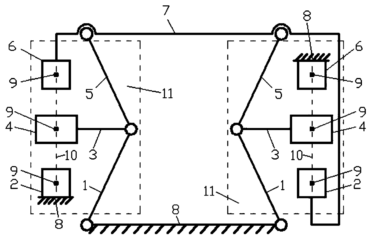
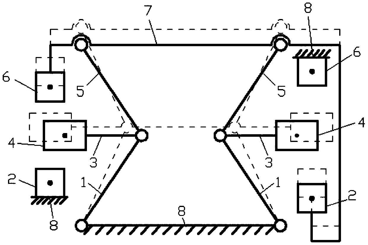
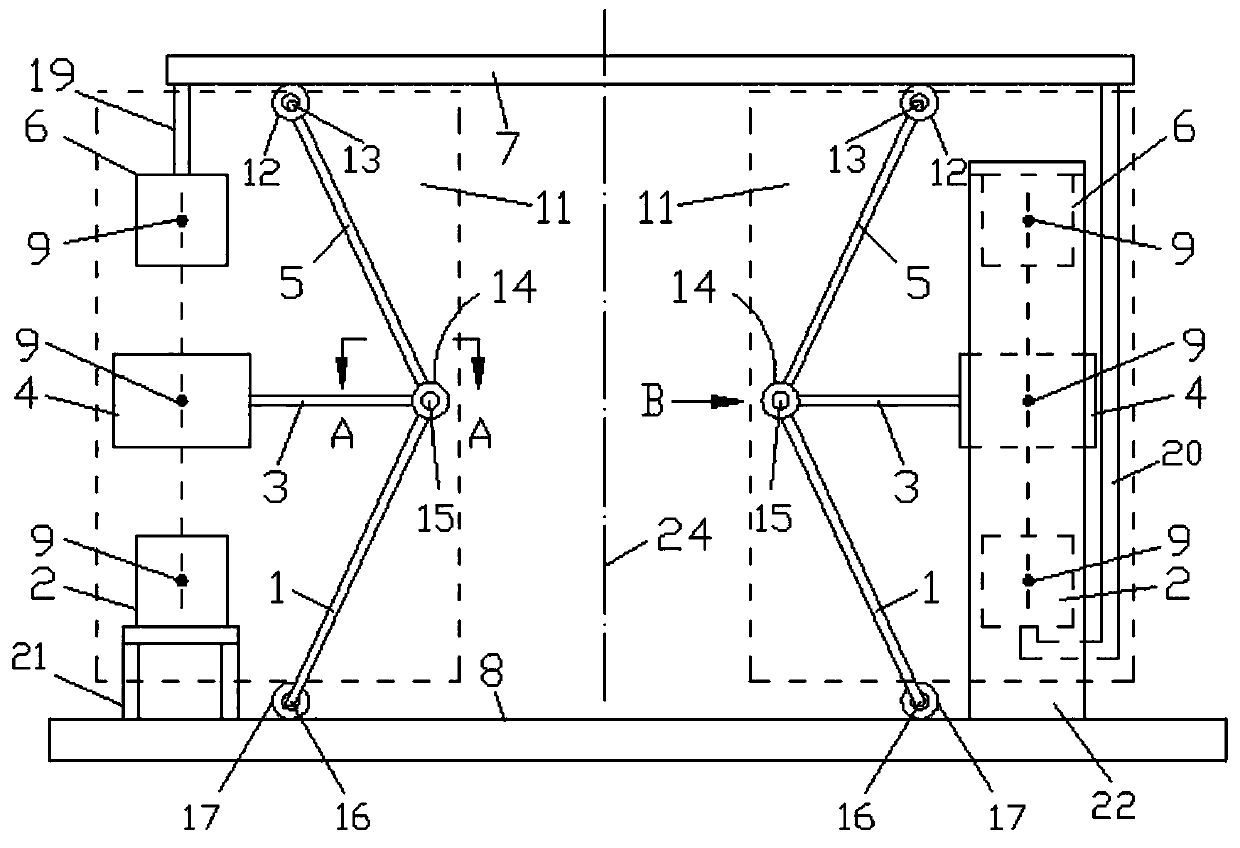
[0030] Depend on Figure 1-Figure 8 ,as well as Figure 10-Figure 12 The shown negative stiffness structure that can provide a stable negative stiffness value includes a support base 7, a base 8, and at least one pair of negative stiffness units 11. In this embodiment, a pair of negative stiffness units 11 are provided. Of course, in different occasions In application, multiple pairs of negative stiffness units 11 can be set according to actual conditions.

[0031] The structure of the negative stiffness unit 11 is as follows: it includes a connecting rod transmission mechanism, an upper magnet 6, a middle magnet 4 and a lower magnet 2, and the upper magnet 6, the middle magnet 4 and the lower magnet 2 are all permanent magnets or electromagnets. , the upper magnet 6, the middle magnet 4 and the lower magnet 2 are all permanent magnets; The magnetic force repels each other, and the middle magnet 4 not only repels the upper magnet 6 magnetic force of its upper side, but also ...


PUM


Abstract

The invention discloses a novel negative stiffness structure capable of providing a stable negative stiffness value, and belongs to the technical field of low-frequency vibration isolating. The novelnegative stiffness structure comprises a supporting seat, a base and at least one pair of negative stiffness units. Each negative stiffness unit comprises a connecting rod transmission mechanism, an upper magnet, a middle magnet and a lower magnet, wherein the upper magnet, the middle magnet and the lower magnet are sequentially arranged at intervals from top to bottom in a corresponding mode, andthe middle magnet repels the upper magnet and the lower magnet. Each connecting rod transmission mechanism comprises an upper connecting rod, a middle connecting rod and a lower connecting rod. The top ends of the upper connecting rods are connected with the supporting seat in a hinged mode, and the bottom ends of the upper connecting rods are connected with the middle connecting rods in a hingedmode. The middle connecting rods are fixedly connected with the middle magnets. The top ends of the lower connecting rods are connected with the middle connecting rods in a hinged mode, and the bottom ends of the lower connecting rods are connected with the base in a hinged mode.

Description

technical field [0001] The invention belongs to the technical field of low-frequency vibration isolation, and in particular relates to a negative stiffness structure capable of providing stable negative stiffness values. Background technique [0002] With the rapid development of science and technology, the optical industry, photosensitive chemistry, aerospace and many other fields are developing towards unprecedented high precision, which accordingly puts forward more stringent requirements for the working environment. Vibration has always been an unavoidable unfavorable factor in the process of machining and manufacturing and precision instrument measurement and control. It not only generates noise, but also reduces production accuracy and even shortens product life. In precision and ultra-precision machining and measurement and control, the hazards of low-frequency and ultra-low-frequency vibration are particularly prominent. [0003] In order to eliminate the hazards of...

Claims


Application Information

Patent Timeline
Patent Type & Authority Patents(China)
IPC IPC(8): F16F6/00
CPCF16F6/005
Inventor 王卫荣张子文葛新方
Owner HEFEI UNIV OF TECH
Learn More