Supercharge Your Innovation With Domain-Expert AI Agents!

Differential force trigger type precise irrigation water quantity measuring device

A technology of precise irrigation and metering device, applied in the direction of measurement device, volume measurement, measurement capacity, etc., can solve the problems of increasing the burden on farmers, low measurement accuracy, and high investment cost, to ensure long-term stable work, quick trigger action, adaptability strong effect

Active Publication Date: 2018-09-14
HOHAI UNIV
View PDF12 Cites 2 Cited by
  • Summary
  • Abstract
  • Description
  • Claims
  • Application Information

AI Technical Summary

Problems solved by technology

[0003] The measurement of irrigation water is a basic and key technology. Traditional Parshall water measuring tanks, U-shaped water measuring tanks and other water measuring devices are only suitable for measuring large water volumes such as main canals and ditches, and are used to realize open channel water delivery in surface water irrigation areas. measurement, but the measurement accuracy of such devices is generally not high
However, some large-scale precision flow devices, such as ultrasonic flowmeters and infrared flowmeters, have high measurement accuracy, but they have high investment costs, complicated installation and high maintenance costs, which will increase the burden on farmers.

Method used


Image

  • Differential force trigger type precise irrigation water quantity measuring device
  • Differential force trigger type precise irrigation water quantity measuring device
  • Differential force trigger type precise irrigation water quantity measuring device

Examples


Embodiment 2

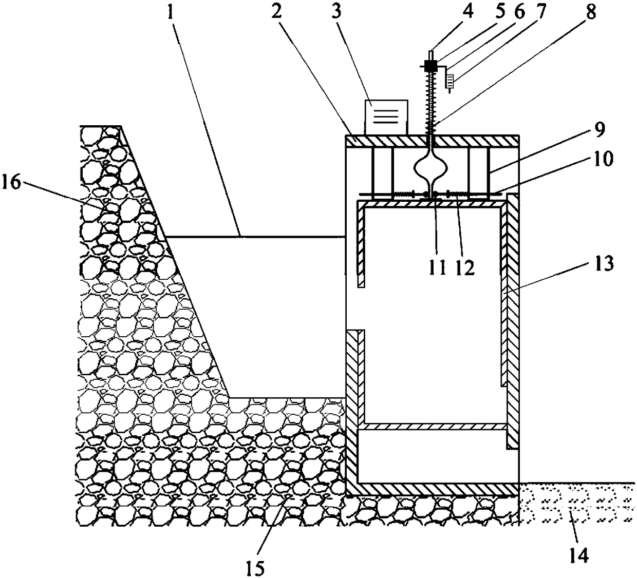
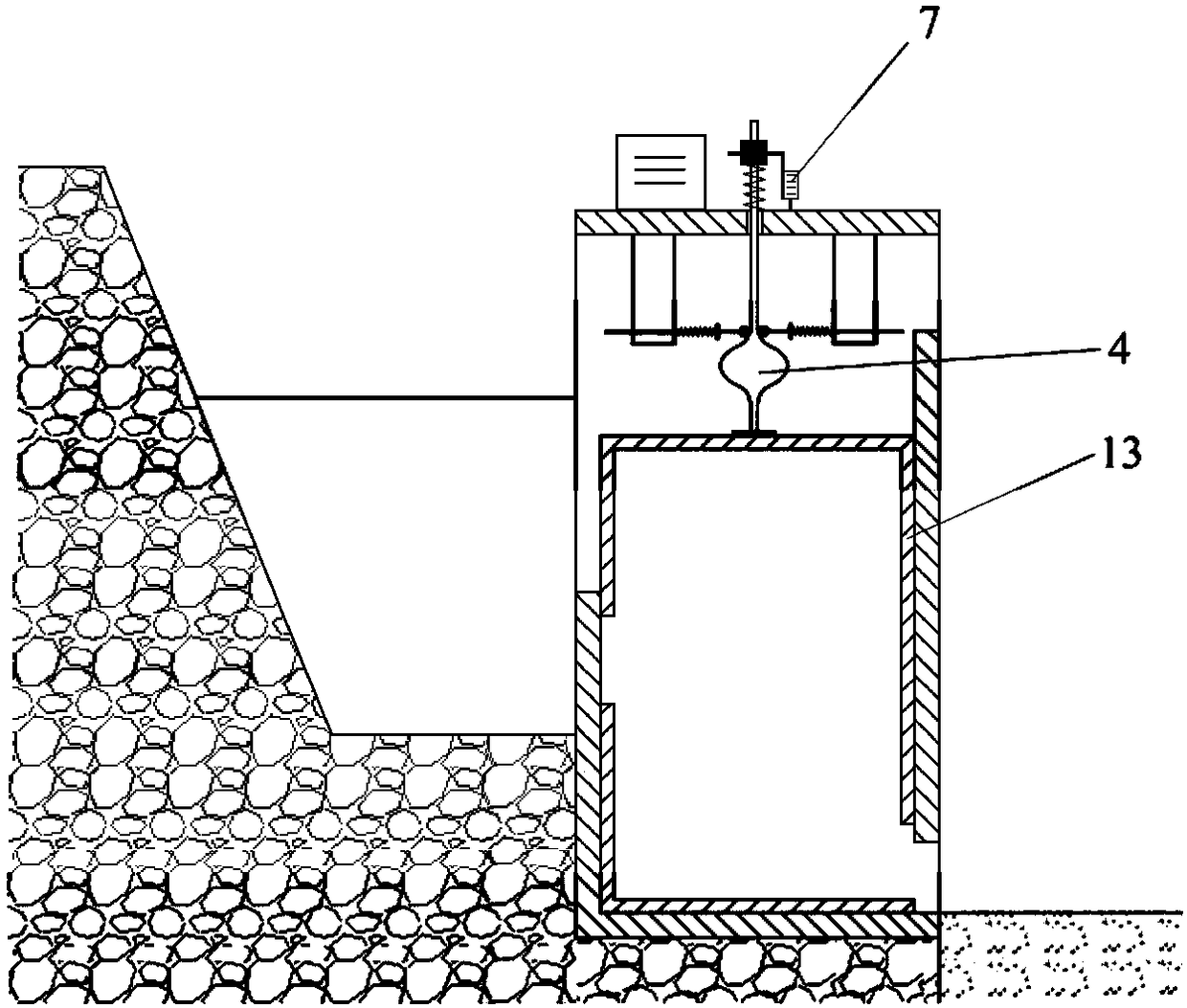
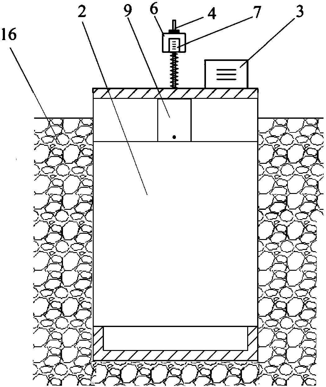
[0046] The difference from Embodiment 1 is that the lifting control rod 4 in this embodiment includes a control rod, and the control rod includes a threaded segment on the upper side and a straight guide rail segment 19 on the lower side, and the lifting control spring 8 is threaded Connect the threaded section, the middle end of the straight guide rail section 19 takes the axis of the control rod as the base point and bulges outwards in the circumferential direction to form a sphere, and several guide grooves 25 are provided on the sphere; the depth of the guide groove 25 is It is 5-8mm.

[0047] Further, the lift control device also includes several transverse limit mechanisms, which are distributed at equal intervals along the circumferential direction with the axis of the lift control rod 4 as the center line, and the transverse limit mechanisms include top Rod 10, ejector rod bracket 9, roller 11, balance spring 12, balance adjustment nut 21 for adjusting the elastic forc...


PUM


Abstract

The invention discloses a differential force trigger type precise irrigation water quantity measuring device. The upper end of a lifting control device is fixedly arranged on an outer box, and the lower end of the lifting control device extends into the outer box to be fixedly connected to the top of an inner box; a first water inlet and a second water inlet which cooperate with each other are formed in the upper end or the middle end of the water inlet side of the inner box and the water inlet side of the outer box respectively, and a first water outlet and a second water outlet which cooperate with each other are formed in the lower end of the water outlet side of the inner box and the lower end of the water outlet side of the outer box respectively; the lifting control device lifts theinner box upwards, the first water inlet and the second water inlet are at least partially overlapped, and water in a ditch protection slope enters the inner box; when the quantity of the water in theinner box gradually increases and the gravity of the inner box exceeds downward resistance, the inner box descends and stays in a water outlet state, the first water outlet and the second water outlet are at least partially overlapped, and the water in the inner tank flows into farmland. The total water quantity is calculated by accumulating the water quantity each time and the lifting frequencyof a water tank, and the quantity of the water for irrigating a field is accurately measured, so that improvement of the utilization efficiency of water resources and intelligent control over the quantity of the water for irrigation are achieved.

Description

technical field [0001] The invention relates to a differential trigger type precision irrigation water metering device, which belongs to the technical field of irrigation water metering devices. Background technique [0002] In today's society, agricultural water consumption is a major consumer of water resources. In recent years, the construction of agricultural water-saving projects has achieved certain results. However, the extensive and inefficient use of agricultural irrigation is still widely used at present, which exacerbates the shortage of water resources to a certain extent. Practice has proved that the construction of agricultural water metering facilities and the metering, charging and control of agricultural water use are effective measures for sustainable agricultural development and an important part of the construction of a water-saving society. However, due to the traditional concept of agricultural water use in my country for a long time, there are few met...

Claims


Application Information

Patent Timeline
Patent Type & Authority Applications(China)
IPC IPC(8): G01F11/26
CPCG01F11/262G01F11/267
Inventor 饶磊王沛芳王超
Owner HOHAI UNIV
Features
  • R&D
  • Intellectual Property
  • Life Sciences
  • Materials
  • Tech Scout
  • Unparalleled Data Quality
  • Higher Quality Content
  • 60% Fewer Hallucinations
Learn More