

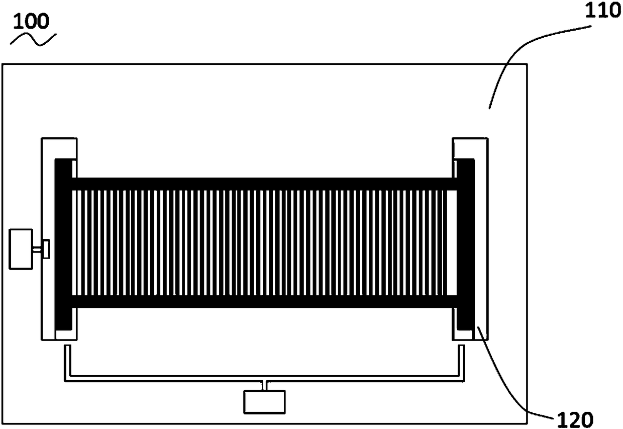
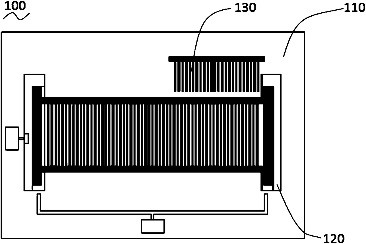
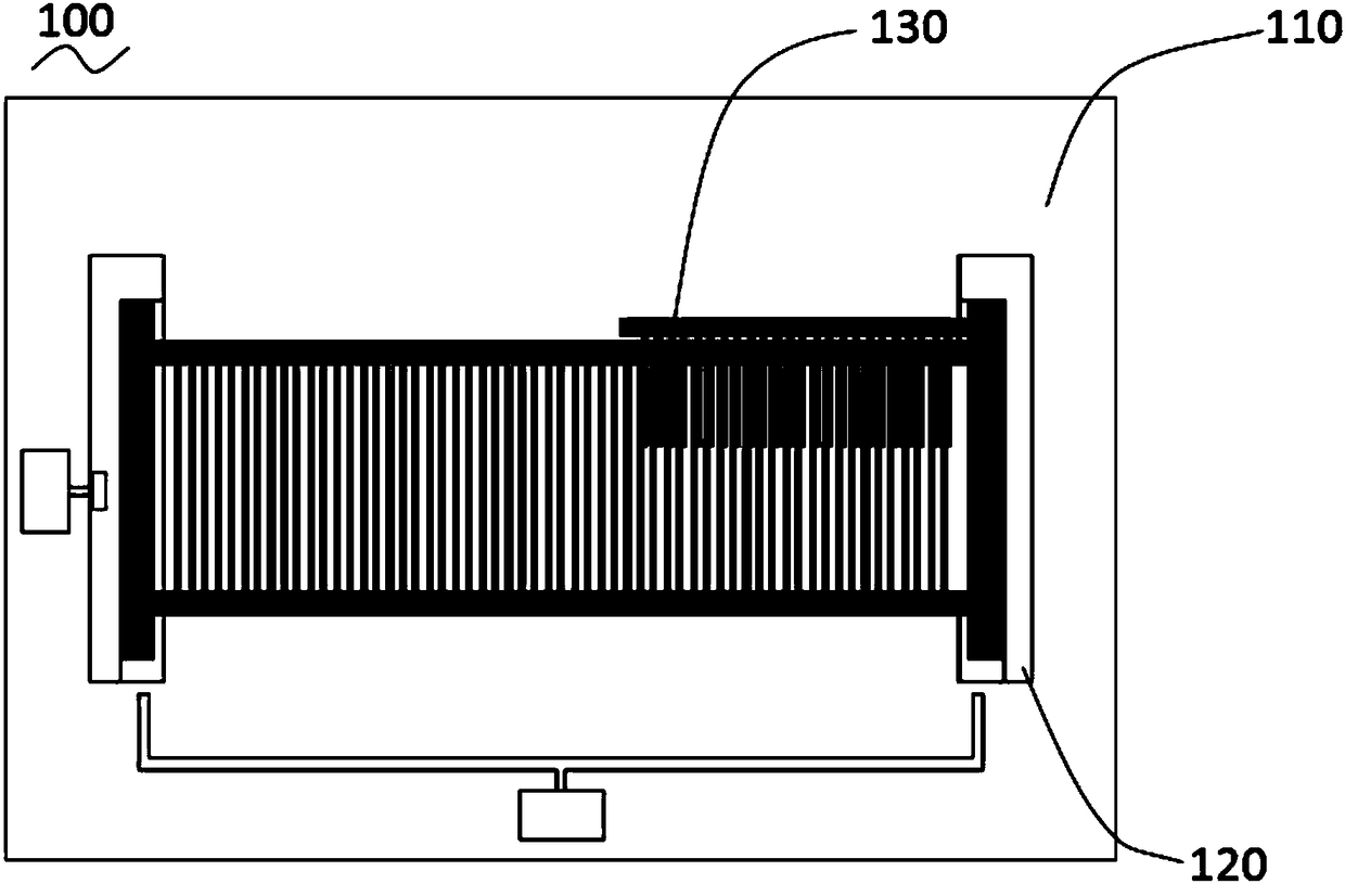
Silicon wafer separator
A slicing machine, silicon wafer technology, applied in sustainable manufacturing/processing, electrical components, climate sustainability, etc. Sharding efficiency, the effect of realizing full automation, reducing the probability of fragmentation and cracking
- Summary
- Abstract
- Description
- Claims
- Application Information
AI Technical Summary
Problems solved by technology
Method used
Image

Examples
Embodiment Construction
[0019] In order to facilitate the understanding of the present invention, the present invention will be described more fully below with reference to the associated drawings. Preferred embodiments of the invention are shown in the accompanying drawings. However, the present invention can be embodied in many different forms and is not limited to the embodiments described herein. On the contrary, these embodiments are provided to make the understanding of the disclosure of the present invention more thorough and comprehensive.
[0020] It should be noted that when an element is referred to as being “fixed” to another element, it can be directly on the other element or there can also be an intervening element. When an element is referred to as being "connected to" another element, it can be directly connected to the other element or intervening elements may also be present.
[0021] Unless otherwise defined, all technical and scientific terms used herein have the same meaning as...
PUM
 Abstract
Description
Claims
Application Information