A patch antenna structure with adjustable pattern and antenna feeder board

A patch antenna and antenna feeder technology, applied in antenna grounding switch structure connection, antenna, antenna coupling, etc., can solve the problems of omnidirectional and directional switching, large antenna size, high cost, etc., and achieve convenient layout and control The effect of short circuit traces and small size

Active Publication Date: 2020-12-08
SHENZHEN SAMSUNG COMM TECH RES +1
View PDF5 Cites 0 Cited by
  • Summary
  • Abstract
  • Description
  • Claims
  • Application Information

AI Technical Summary

Problems solved by technology

Among them, the change of physical shape, especially the change of the overall shape of the antenna (bending, folding, etc.) is difficult to realize, which has a great disadvantage compared to software switching; in addition, base station antennas require different types of patterns when they are installed on the wall and on the ceiling. The antenna, that is, the ceiling needs an omnidirectional antenna, while the wall needs a directional antenna
Multi-antenna technology results in larger antenna size and higher cost
In addition, the currently known technical solutions for changing the shape of the radiation unit to reconstruct the pattern cannot realize omnidirectional and directional switching

Method used


Image

  • A patch antenna structure with adjustable pattern and antenna feeder board
  • A patch antenna structure with adjustable pattern and antenna feeder board

Examples


Embodiment Construction

[0020] The following will clearly and completely describe the technical solutions in the embodiments of the present invention with reference to the accompanying drawings in the embodiments of the present invention. Obviously, the described embodiments are only some, not all, embodiments of the present invention. Based on the embodiments of the present invention, all other embodiments obtained by persons of ordinary skill in the art without creative efforts fall within the protection scope of the present invention.

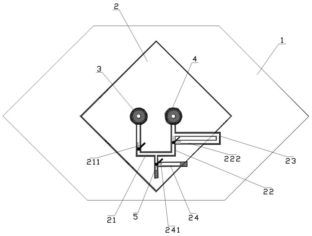
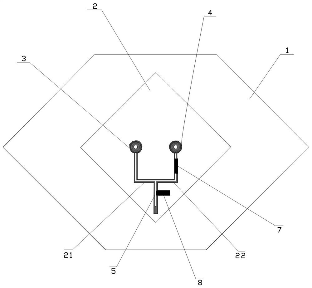
[0021] see figure 1 , is Embodiment 1 of the patch antenna structure with adjustable pattern in the present invention.

[0022] The patch antenna structure with adjustable pattern in this embodiment includes: a metal floor 1, a feed patch 2 is connected to the metal floor 1, a first feed line 21 is provided on the feed patch 2, and a first feed line 21 is connected to the second A first feeding point 3 in a feeding line 21, a second feeding line 22 and a second fe...


PUM


Abstract

The invention discloses a patch antenna structure with an adjustable directional diagram. The patch antenna structure comprises a metal floor. A feed patch is connected to the metal floor and is provided with a first feeder line, a feeding point connected to the first feeder line, a second feeder line, and a second feeding point connected to the second feeder line. The first feeder line and the second feeder line intersect at a node, wherein the length of the first feeder line between the node and the first feeding point is equal to that of the second feeder line between the node and the second feeding point. A switching component for changing the relative phase between the first feeding point and the second feeding point is disposed in the first feeder line and / or the second feeder line.The invention also discloses an antenna feeder board. The patch antenna structure with an adjustable directional diagram and the antenna feeder board of the invention can switch or scan two directional diagrams by using one antenna, are simplified in design, low in cost, and reasonable in structural design, effectively control the direction of the circuit, and have less influences on the radiationdirectional diagram.

Description

technical field [0001] The invention relates to the field of communication equipment, in particular to a patch antenna structure with an adjustable pattern and an antenna feeder board. Background technique [0002] In the prior art, omnidirectional and directional switching technologies can be classified into the following two categories: changing the physical shape of the antenna radiation unit; switching and coordination of multiple antenna groups. Among them, the change of physical shape, especially the change of the overall shape of the antenna (bending, folding, etc.) is difficult to realize, which has a great disadvantage compared to software switching; in addition, base station antennas require different types of patterns when they are installed on the wall and on the ceiling. Antennas, that is, ceiling-mounted antennas require omnidirectional antennas, while wall-mounted antennas require directional antennas. The multi-antenna technology results in larger antenna si...

Claims


Application Information

Patent Timeline
Patent Type & Authority Patents(China)
IPC IPC(8): H01Q1/50H01Q1/52H01Q3/30H01Q1/48
CPCH01Q1/48H01Q1/50H01Q1/52H01Q3/30
Inventor 靳炉魁牛兵建蔡磊
Owner SHENZHEN SAMSUNG COMM TECH RES
Why Eureka
Try Eureka