
Interlocking mechanism for high-voltage switch cabinet

A technology of high-voltage switchgear and interlock mechanism, which is applied in the direction of pull-out switchgear, switchgear, electrical components, etc., and can solve problems such as inability to directly interlock the protective door behind the cabinet, personal and equipment accidents, troublesome operation of program locks, etc. , to achieve the effect of saving manpower and material resources, strong linkage and low cost

Active Publication Date: 2018-09-14
QUANZHOU DAXIYANG ELECTRIC POWER TECH CO LTD
View PDF5 Cites 7 Cited by
  • Summary
  • Abstract
  • Description
  • Claims
  • Application Information

AI Technical Summary

Problems solved by technology

However, due to the troublesome operation of the program lock and the slow unlocking, many substations are reluctant to adopt it, which has led to the widespread use of mechanical simple five-proof interlocks. However, this mechanism cannot be directly interlocked with the protective door at the back of the cabinet, so that The door can only rely on the hanging lock to prevent mistaken entry
However, it is very likely that the operation and maintenance personnel will accidentally enter the adjacent live cabinet due to the staggered opening of the back door, causing personal and equipment accidents, and the process of unlocking the lock is cumbersome, and the key must be kept well. There are many uncontrollable factors.

Method used


Image

  • Interlocking mechanism for high-voltage switch cabinet
  • Interlocking mechanism for high-voltage switch cabinet
  • Interlocking mechanism for high-voltage switch cabinet

Examples


Embodiment Construction

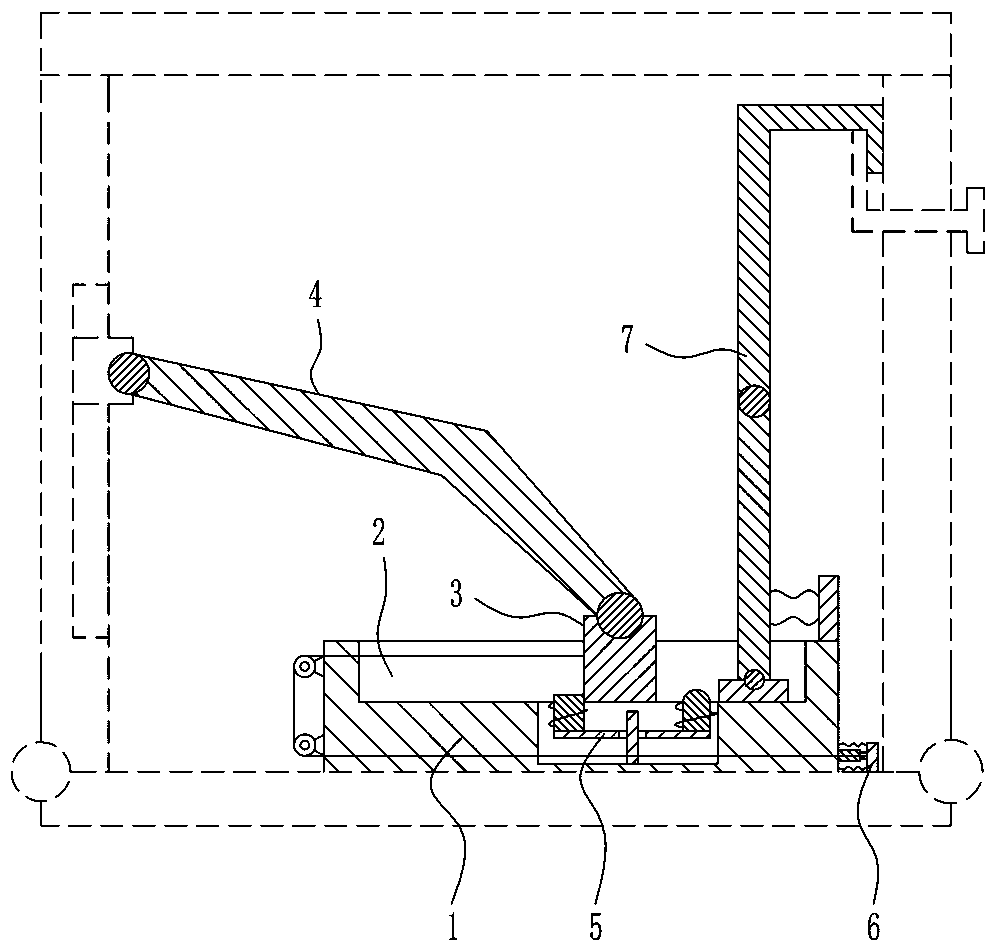
[0023] The present invention will be further described in conjunction with the accompanying drawings and specific embodiments.

[0024] In describing the present invention, it is to be understood that the terms "center", "upper", "lower", "front", "rear", "left", "right", "vertical", "horizontal", The orientation or positional relationship indicated by "top", "bottom", "inner", "outer", "clockwise", "counterclockwise" etc. is based on the attached figure 1 The orientations or positional relationships shown are only for the convenience of describing the present invention and simplifying the description, and do not indicate or imply that the referred device or element must have a specific orientation, be constructed and operated in a specific orientation, and therefore cannot be construed as an important aspect of the present invention. limits.

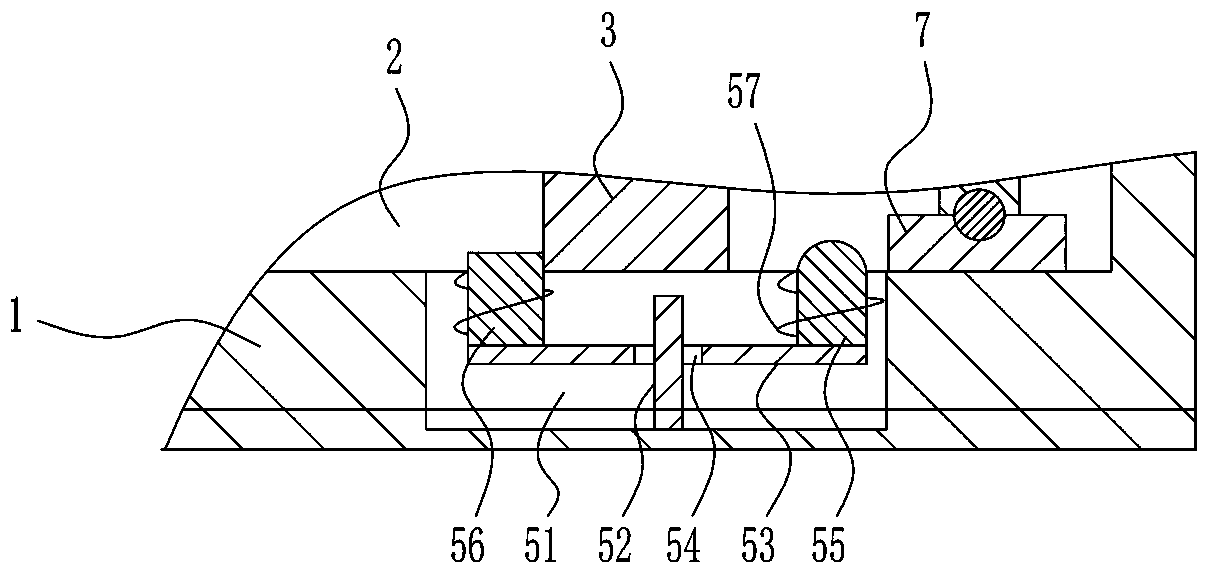
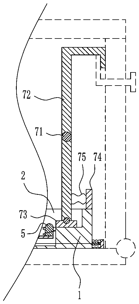
[0025] Such as Figure 1-7 As shown, an interlocking mechanism for a high-voltage switchgear includes a mounting block 1, a slider 3...


PUM


Abstract

The invention discloses an interlocking mechanism for a high-voltage switch cabinet. The interlocking mechanism for the high-voltage switch cabinet comprises a mounting block, a sliding block, a connecting rod, a back limiting mechanism, a front limiting mechanism and a trigger mechanism; a sliding groove is formed in the mounting block; the sliding groove is in sliding connection with the slidingblock; the sliding block is movably connected with the connecting rod; and the back limiting mechanism, the front limiting mechanism and the trigger mechanism are arranged on the mounting block. Thesafety problem caused by misoperation is avoided; furthermore, the interlocking mechanism for the high-voltage switch cabinet does not need other operation, is simple, convenient and rapid and can beimplemented by cooperating with normal door opening / closing action; and the interlocking mechanism for the high-voltage switch cabinet has a high linkage property and adopts a pure mechanical structure, and the cost of all the structural parts is low, so the cost problem caused by the use of a program lock is avoided.

Description

technical field [0001] The invention belongs to the technical field of high-voltage electrical equipment, and in particular relates to an interlocking mechanism for a high-voltage switch cabinet. Background technique [0002] In the high-voltage complete switchgear, in order to prevent misoperation and mistakenly entering the charged interval, the safety interlock is usually completed by changing different keys with a program lock. In order to prevent the operator from mistakenly entering the live switch cabinet, it is required that the front and rear doors of the switch cabinet must be closed and opened in strict accordance with the prescribed procedures. When closing the door, the back door of the switch cabinet should be closed first, and then the front door of the switch cabinet should be closed; when the door is opened, the operation sequence should be reversed. However, due to the troublesome operation of the program lock and the slow unlocking, many substations are r...

Claims


Application Information

Patent Timeline
Patent Type & Authority Applications(China)
IPC IPC(8): H02B11/133
CPCH02B11/133
Inventor 王汉钦
Owner QUANZHOU DAXIYANG ELECTRIC POWER TECH CO LTD
Learn More