Flexible anti-impact bionic pulled and pressed body knee joint

An impact-resistant, knee-joint technology, applied in the field of robotics, can solve problems such as increased energy consumption, easy damage to rigid knee joints, and joint impact

Active Publication Date: 2018-09-18
JILIN UNIV
View PDF7 Cites 12 Cited by
  • Summary
  • Abstract
  • Description
  • Claims
  • Application Information

AI Technical Summary

Problems solved by technology

During the high-speed dynamic movement of the robot such as walking or running at high speed, the hinged knee joint is often subjected to various types of loads such as large tension and compression, shearing, bending and torsion, so it is necessary to achieve joint stability through real-time precise control, and then It also complicates the control sy

Method used


Image

  • Flexible anti-impact bionic pulled and pressed body knee joint
  • Flexible anti-impact bionic pulled and pressed body knee joint
  • Flexible anti-impact bionic pulled and pressed body knee joint

Examples


Embodiment Construction

[0098] The present invention will be further analyzed below in conjunction with accompanying drawing.

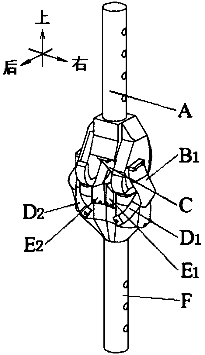
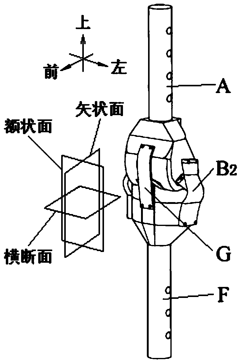
[0099] Such as figure 1 , figure 2 As shown, the present invention consists of bionic femur A, right side bionic flexible lateral ligament B 1 , Left bionic flexible lateral ligament B 2 , bionic flexible anterior cruciate ligament C, right bionic flexible popliteal ligament D 1 , Left bionic flexible popliteal ligament D 2 , Right bionic flexible posterior cruciate ligament E 1 , Left bionic flexible posterior cruciate ligament E 2 , bionic tibia F and bionic flexible patellar ligament G, of which the right bionic flexible lateral ligament B 1 Through its upper end bolt group Ⅰ23, it is threadedly connected with the threaded hole group Ⅲ5 of the bionic femoral condyle 2 in the bionic femur A; the right bionic flexible lateral ligament B 1 Through its lower end bolt group I24, it is threadedly connected with the threaded hole group XI15 of the bionic tibial condyle 1...


PUM

PropertyMeasurementUnit
Thicknessaaaaaaaaaa
Total heightaaaaaaaaaa
Lengthaaaaaaaaaa

Abstract

The invention provides a flexible anti-impact bionic pulled and pressed body knee joint, belonging to the technical field of robots. The flexible anti-impact bionic pulled and pressed body knee jointcomprises pressed bodies (the bionic femur and the bionic tibia) and pulled bodies (the bionic flexible ligaments), wherein the pulled bodies are connected with the pressed bodies, so that a bionic knee joint structure is formed; the prestrain and the material attribute of the pulled bodies are adjustable, so that various speeds and loading states of a bipedal robot can be adapted. The appearancessimulating the human skeleton curve of the bionic femur condyle and the bionic tibia condyle enable the knee joint to be capable of generating the rotation with three degrees of freedom, in the faceof the high speed or large load, the rotation in the frontal plane and the cross section can effectively alleviate the impact of the external force or the moment of force. The pulled bodies and the pressed bodies are connected to form a space three-dimensional topological structure, when disturbance of the external load is applied, the force is transmitted to the other pressed bodies and pulled bodies through the topological structure, finally, a passive self-stabilizing structure without the need of energy input is formed, the multi-dimension mechanical impedance can be resisted, the controlis simplified, and the energy consumption is reduced.

Description

technical field [0001] The invention belongs to the technical field of robots, and in particular relates to a flexible impact-resistant bionic tension-compression body knee joint. Background technique [0002] At present, in order to realize the freedom of movement and stability of the knee joint of the biped robot, the design is simplified as a mechanical hinge connection structure (pin-bearing connection). During the high-speed dynamic movement of the robot such as walking or running at high speed, the hinged knee joint is often subjected to various types of loads such as large tension and compression, shearing, bending and torsion, so it is necessary to achieve joint stability through real-time precise control, and then It also complicates the control system of the system and increases energy consumption. In addition, in the process of high-speed dynamic movement, the impact force of the robot foot on the ground will often cause a great impact on the joints, so that the ...

Claims


Application Information

Patent Timeline
IPC IPC(8): A61F2/64
CPCA61F2/64
Inventor 梁威任雷钱志辉王坤阳吉巧丽任露泉
Owner JILIN UNIV
Why Eureka
Try Eureka