Reinforcement surface removing equipment containing concrete slag

A concrete and steel bar technology, applied in the field of steel bar surface cleaning equipment, can solve the problems of workers' hand injury, time-consuming and laborious work process, slow speed, etc., and achieve the effect of fast speed, free labor and fast cleaning

Inactive Publication Date: 2018-09-18
汤国忠
View PDF0 Cites 13 Cited by
  • Summary
  • Abstract
  • Description
  • Claims
  • Application Information

AI Technical Summary

Problems solved by technology

[0006] In order to overcome the disadvantages of slow speed, time-consuming and labor-intensive work process, and damage to workers’ hands when cleaning concrete blocks on the surface of steel bars, the technical problem to be solved by the present invention is to provide a fast-working, Rebar surface removal equipment containing concrete slag that saves time and labor and does not cause harm to workers' hands

Method used


Image

  • Reinforcement surface removing equipment containing concrete slag
  • Reinforcement surface removing equipment containing concrete slag
  • Reinforcement surface removing equipment containing concrete slag

Examples


Embodiment 1

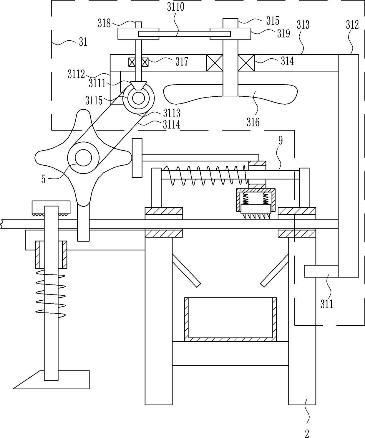
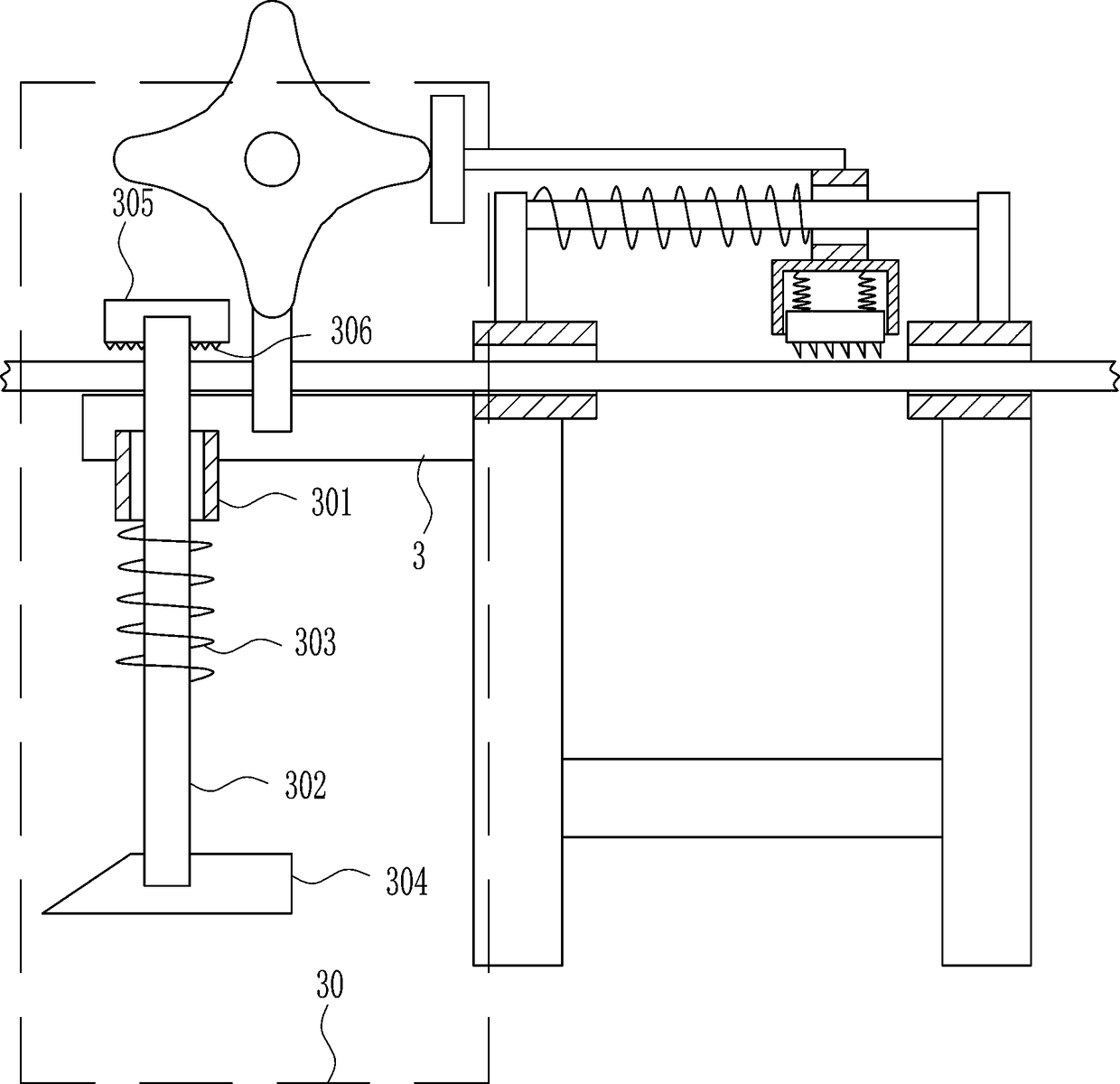
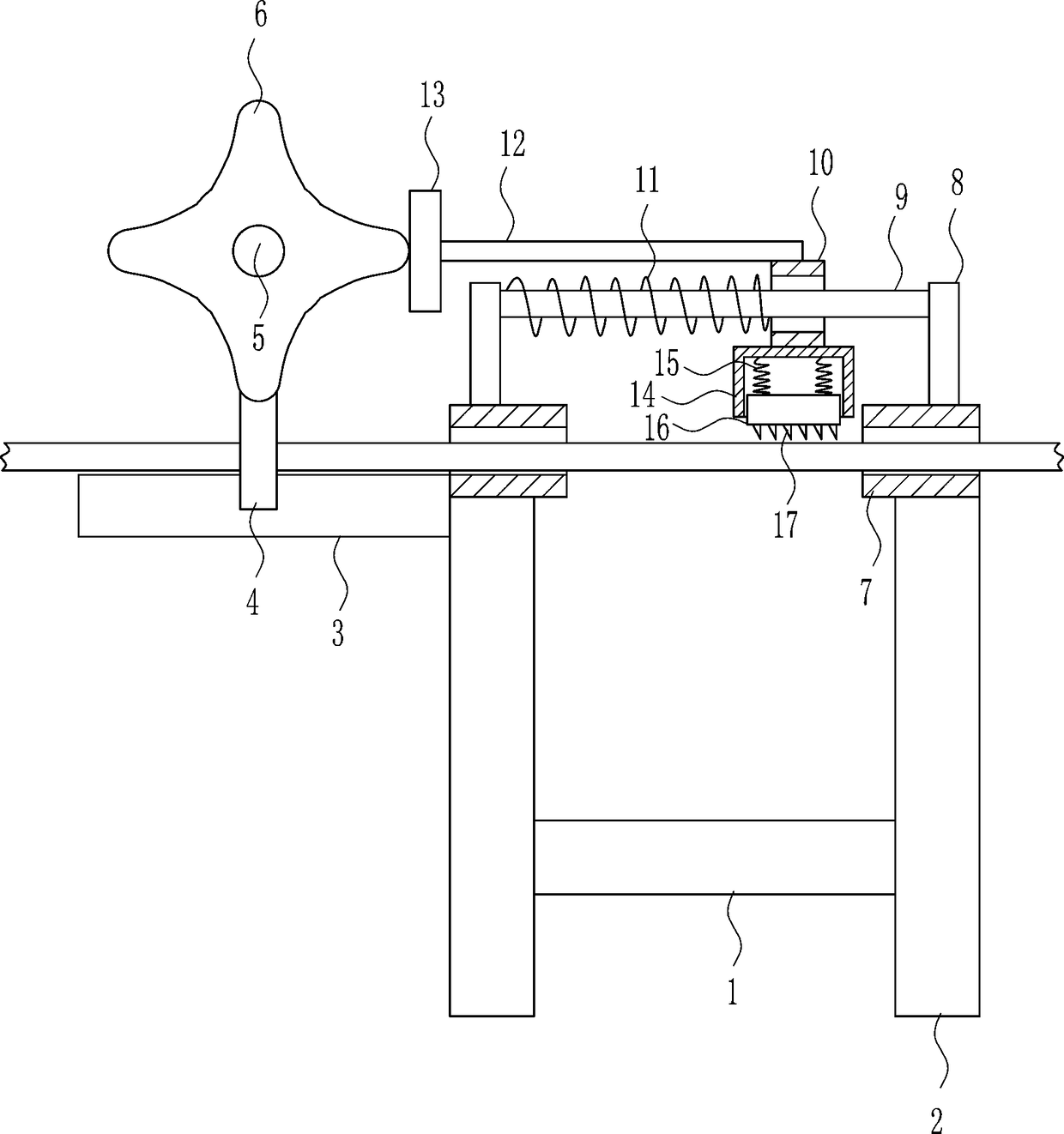
[0028] A rebar surface removal equipment containing concrete slag, such as Figure 1-5As shown, it includes a mounting plate 1, a bracket 2, a fixing plate 3, a support rod 4, an electric wheel 5, a lace cam 6, a sliding sleeve 7, a fixing block 8, a first guide rail 9, a first guide sleeve 10, and a first spring 11. Push rod 12, contact rod 13, mounting sleeve 14, second spring 15, moving block 16 and inverted teeth 17, the left and right ends of the mounting plate 1 are connected to the bracket 2, and the upper left side of the left bracket 2 is connected to the fixed plate 3. The middle part of the front side of the fixed plate 3 is connected to the support rod 4, the upper front side of the support rod 4 is connected to the electric wheel 5, the front side of the electric wheel 5 is connected to the lace cam 6, and the upper end of the bracket 2 is connected to the sliding sleeve 7, the sliding sleeve 7 The upper ends are connected with fixed blocks 8, and the first guide ...

Embodiment 2

[0030] A rebar surface removal equipment containing concrete slag, such as Figure 1-5 As shown, it includes a mounting plate 1, a bracket 2, a fixing plate 3, a support rod 4, an electric wheel 5, a lace cam 6, a sliding sleeve 7, a fixing block 8, a first guide rail 9, a first guide sleeve 10, and a first spring 11. Push rod 12, contact rod 13, mounting sleeve 14, second spring 15, moving block 16 and inverted teeth 17, the left and right ends of the mounting plate 1 are connected to the bracket 2, and the upper left side of the left bracket 2 is connected to the fixed plate 3. The middle part of the front side of the fixed plate 3 is connected to the support rod 4, the upper front side of the support rod 4 is connected to the electric wheel 5, the front side of the electric wheel 5 is connected to the lace cam 6, and the upper end of the bracket 2 is connected to the sliding sleeve 7, the sliding sleeve 7 The upper ends are connected with fixed blocks 8, and the first guide...

Embodiment 3

[0033] A rebar surface removal equipment containing concrete slag, such as Figure 1-5 As shown, it includes a mounting plate 1, a bracket 2, a fixing plate 3, a support rod 4, an electric wheel 5, a lace cam 6, a sliding sleeve 7, a fixing block 8, a first guide rail 9, a first guide sleeve 10, and a first spring 11. Push rod 12, contact rod 13, mounting sleeve 14, second spring 15, moving block 16 and inverted teeth 17, the left and right ends of the mounting plate 1 are connected to the bracket 2, and the upper left side of the left bracket 2 is connected to the fixed plate 3. The middle part of the front side of the fixed plate 3 is connected to the support rod 4, the upper front side of the support rod 4 is connected to the electric wheel 5, the front side of the electric wheel 5 is connected to the lace cam 6, and the upper end of the bracket 2 is connected to the sliding sleeve 7, the sliding sleeve 7 The upper ends are connected with fixed blocks 8, and the first guide...


PUM


Abstract

The invention relates to construction concrete equipment, in particular to reinforcement surface removing equipment containing concrete slag. The reinforcement surface removing equipment containing the concrete slag is high in speed, saves both time and labors in the working process, and cannot injure worker hands. The reinforcement surface removing equipment containing the concrete slag comprisesa mounting plate, brackets, a fixed plate, a support rod, an electric wheel, a flange cam, a slide sleeve, a fixed block, a first guide rail, a first guide sleeve, a first spring, a push rod and thelike; the brackets are connected to the left and right ends of the mounting plate; and the fixed plate is connected above the left side of the bracket on the left side. The reinforcement surface removing equipment containing the concrete slag achieves the effects of high speed, time and labor saving in the working process and incapability of injuring the worker hands, and can quickly remove reinforcement surfaces through adopting a mode of the flange cam driving reverse teeth to scrape concrete blocks on the reinforcement surfaces without needing labors so as to liberate the labors.

Description

technical field [0001] The invention relates to construction concrete equipment, in particular to equipment for removing steel bars containing concrete slag. Background technique [0002] Concrete: refers to the collective name of engineering composite materials in which aggregates are cemented into a whole by cementitious materials. Generally speaking, the term concrete refers to the cement concrete obtained by using cement as the cementitious material, sand and stone as the aggregate; mixed with water (may contain admixtures and admixtures) in a certain proportion, and stirred. Concrete, which is widely used in civil engineering. [0003] At present, when cleaning the remaining concrete blocks on the surface of the steel bars on the building, most of them use manual hand-held files to clean the surface of the steel bars. When cleaning, it can also cause injury to workers' hands. [0004] Therefore urgently need to develop a kind of fast, time-saving and labor-saving wor...

Claims


Application Information

Patent Timeline
Patent Type & Authority Applications(China)
IPC IPC(8): B08B1/00B08B1/02B08B5/02B08B13/00
CPCB08B1/005B08B1/002B08B1/02B08B5/02B08B13/00
Inventor 汤国忠
Owner 汤国忠
Why Eureka
Try Eureka