Test tube clamping unit and automatic test tube cleaning device

An automatic cleaning and test tube clamping technology, which is applied in the direction of cleaning hollow objects, cleaning methods and utensils, chemical instruments and methods, etc., can solve the problems of low cleaning efficiency, human injury, difficult test tubes, etc. simple structure

Inactive Publication Date: 2018-09-18
UNIV OF SHANGHAI FOR SCI & TECH
View PDF7 Cites 8 Cited by
  • Summary
  • Abstract
  • Description
  • Claims
  • Application Information

AI Technical Summary

Problems solved by technology

[0002] In the fields of medicine, chemistry, pharmaceuticals, etc., the cleaning of test tubes is a very difficult problem. After the test tubes with reagents are used, the test tubes need to be rinsed. If they are not cleaned in time, when the reagents solidify, the test tubes will be washed again. Very difficult, serious test tubes will be scrapped, in addition, the reagents remaining in the test tubes will also cause certain pollution to the working environment such as the laboratory
[0003] When manually cleaning the test tube, the test tube is held by hand, and the test tube is easy to shake. If you are not careful, it will corrode the hands, eyes and other organs of the cleaning personnel, causing harm to the human body, and the cleaning efficiency is low and the cleaning effect is poor.
Due to the special shape of the test tube, the existing test tube cleaning device has problems such as the test tube is difficult to clamp and fix, resulting in unstable test tubes and unclean cleaning.

Method used


Image

  • Test tube clamping unit and automatic test tube cleaning device
  • Test tube clamping unit and automatic test tube cleaning device
  • Test tube clamping unit and automatic test tube cleaning device

Examples


Embodiment Construction

[0027] The idea, specific structure and technical effects of the present invention will be further described below in conjunction with the accompanying drawings, so as to fully understand the purpose, features and effects of the present invention.

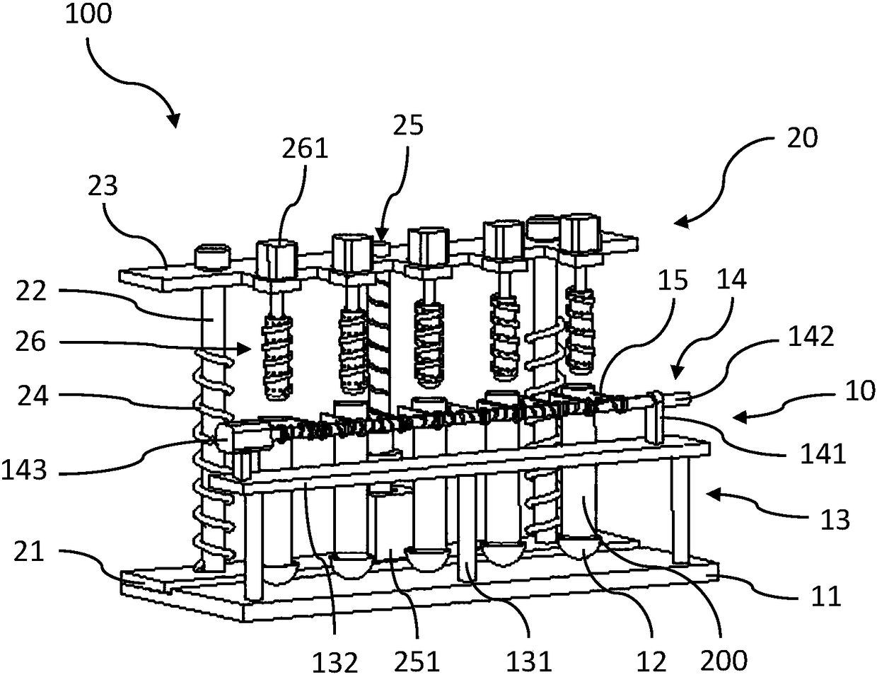
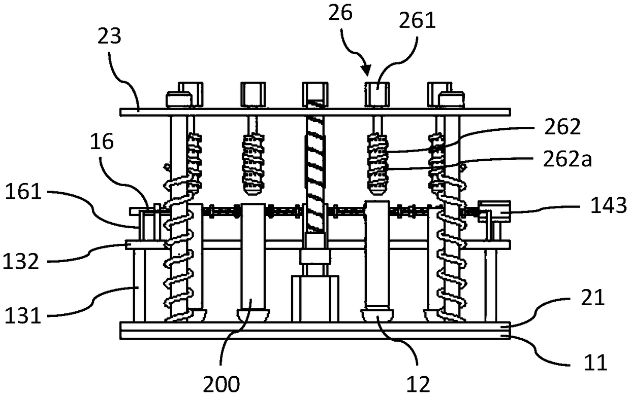
[0028] figure 1 It is a schematic diagram of the three-dimensional structure of the test tube automatic cleaning device in the embodiment of the present invention; figure 2 It is the rear view of the test tube automatic cleaning device in the embodiment of the present invention.

[0029] Such as figure 1 and figure 2 As shown, the test tube automatic cleaning device 100 in this embodiment is used to clamp, fix and clean a plurality of test tubes 200 at the same time, and includes a test tube clamping unit 10 and a cleaning unit 20 .

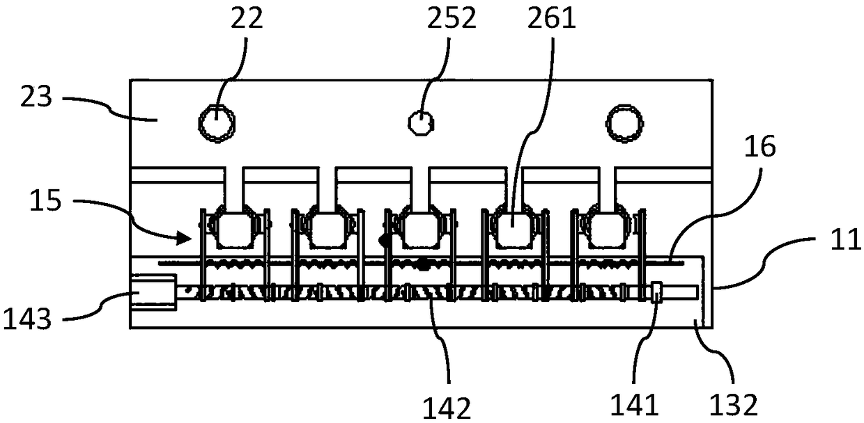
[0030] image 3 is a plan view of the test tube holding unit in the embodiment of the present invention.

[0031] Such as Figure 1 to Figure 3 As shown, the test tube clamping unit 10 is used...


PUM


Abstract

The invention provides a test tube clamping unit and an automatic test tube cleaning device with the test tube clamping unit. The test tube clamping unit is used for clamping and fixing multiple testtubes simultaneously and comprises a first base, multiple test tube supporting blocks, an installing rack, a first driving assembly and test tube clamps; the multiple test tube supporting blocks are arranged on the first base at intervals, and the test tube supporting blocks are provided with grooves which are matched with the shapes of the bottoms of test tubes and used for supporting and positioning the test tubes; the installing rack is fixedly arranged on the first base; the first driving assembly is fixedly arranged on the installing rack; and the number of the test tube clamps is the same as that of the test tube supporting blocks, and the test tube clamps are installed on the first driving assembly, arranged to correspond to the multiple test tube supporting blocks one to one and driven by the first driving assembly to be folded or unfolded to clamp or loosen the opening portions of the test tubes. The automatic test tube cleaning device is used for clamping, fixing and cleaningthe multiple test tubes simultaneously and comprises the test tube clamping unit used for clamping and fixing the test tubes and a cleaning unit which is fixedly connected with the test tube clampingunit and used for cleaning the test tubes.

Description

technical field [0001] The invention belongs to the technical field of cleaning devices for experimental instruments, and in particular relates to a test tube clamping unit and a test tube automatic cleaning device comprising the test tube clamping unit. Background technique [0002] In the fields of medicine, chemistry, pharmaceuticals, etc., the cleaning of test tubes is a very difficult problem. After the test tubes with reagents are used, the test tubes need to be rinsed. If they are not cleaned in time, when the reagents solidify, the test tubes will be washed again. Very difficult, serious test tubes will be scrapped, in addition, the reagents remaining in the test tubes will also cause certain pollution to the working environment such as the laboratory. [0003] When manually cleaning the test tube, the test tube is held by hand, and the test tube is easy to shake. If you are not careful, it will corrode the hands, eyes and other organs of the cleaning personnel, caus...

Claims


Application Information

Patent Timeline
Patent Type & Authority Applications(China)
IPC IPC(8): B08B9/36
CPCB08B9/36
Inventor 宫赤坤张吉祥
Owner UNIV OF SHANGHAI FOR SCI & TECH
Why Eureka
Try Eureka