Assembling screw device for roof rack

A technology for car luggage racks and screws, applied in metal processing, metal processing equipment, manufacturing tools, etc., can solve problems such as heavy workload, error-prone, and inability to deliver in place, avoiding manual measurement, ensuring accuracy, and improving group performance. Efficiency effect

Pending Publication Date: 2018-09-18
NINGBO MINTH AUTOMOTIVE PARTS RES&DEV CO LTD
View PDF0 Cites 0 Cited by
  • Summary
  • Abstract
  • Description
  • Claims
  • Application Information

AI Technical Summary

Problems solved by technology

[0002] With the development of the automobile industry, luggage racks will be installed on many SUV cars, here image 3 As shown, the car luggage rack generally includes an aluminum tube body 1, three base blocks 2 and three nut delivery parts 3, where the three base blocks are respectively provided with one at the left, middle and right positions of the aluminum tube body 1, and the nuts The conveying part 3 is mainly used to convey the nut parts. There are screws on the base block 2. When installing the base block 2, three nut conveying parts 3 need to be transported into the aluminum tube body 1 and aligned with the respective base blocks. Assemble and lock with the screw on the base block. There are strict requirements on the torque value of the screw when assembling and locking. In the prior art, the torque value was measured and recorded separately by hand. The workload is heavy and error-prone, and each The torque value is not traceable and cannot meet the needs of the existing high-speed automatic production. At the same time, the existing technology cannot transport the nuts in place when assembling and conveying the conveying parts, resulting in the inability to assemble with the screws, which seriously affects the assembly efficiency of the automobile luggage rack.

Method used


Image

  • Assembling screw device for roof rack
  • Assembling screw device for roof rack
  • Assembling screw device for roof rack

Examples


Embodiment Construction

[0014] The following are specific embodiments of the present invention and in conjunction with the accompanying drawings, the technical solutions of the present invention are further described, but the present invention is not limited to these embodiments.

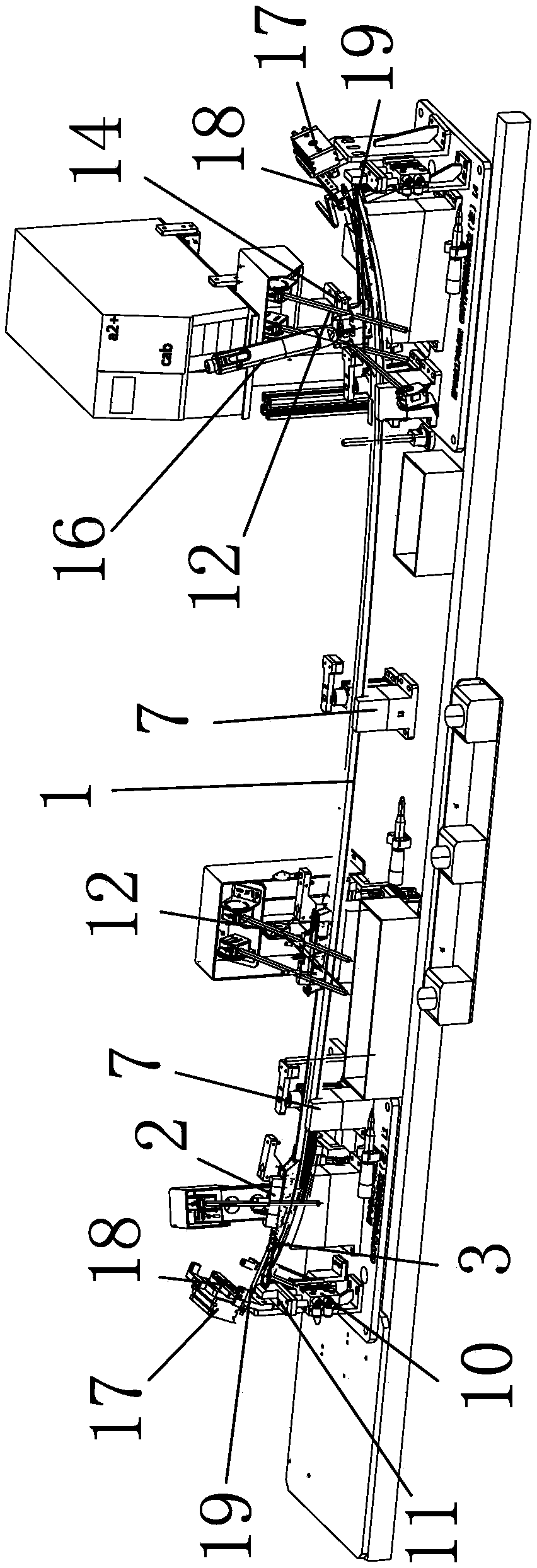
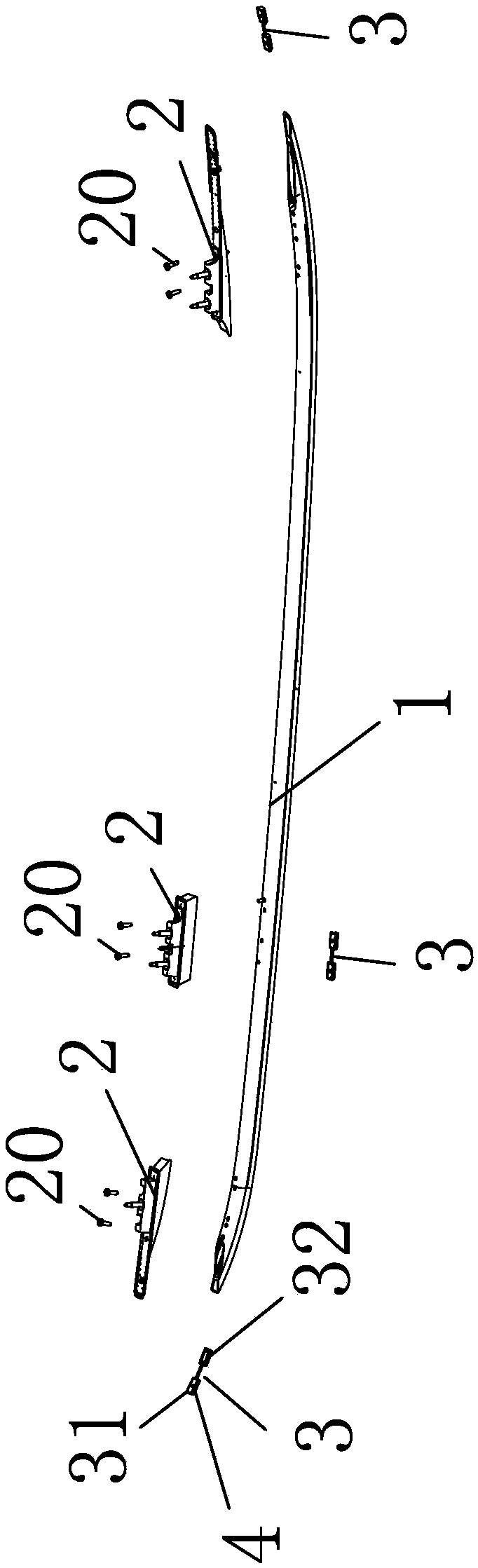
[0015] In the figure, the aluminum tube body 1; the base block 2; the nut conveying part 3; the accommodation groove part 31; the connecting part 32; the nut part 4; the main frame 5; Binder rotating rod 9; end cylinder 10; end limiter 11; screw detection head 12; position control cylinder 13; position control rod 14; blocking head 15; screwdriver 16; air blowing cylinder 17; Part 18; blowing rod 19; screw 20.

[0016] Such as figure 1 and figure 2 As shown, the automobile luggage rack assembly screw device is used to assemble the automobile luggage rack. The automobile luggage rack has an aluminum tube body 1, three base blocks 2 and three nut delivery parts 3, and the aluminum tube body 1 The inside is a hollow stru...


PUM


Abstract

The invention belongs to the technical field of production equipment of automobile parts, and provides an assembling screw device for a roof rack. The device comprises a main frame, wherein an assembling platform is arranged on the main frame; a plurality of positioning pedestals are transversely arranged at intervals on the assembling platform, and an aluminum pipe body to be assembled is positioned on the positioning pedestals; each of the left end, the intermediate end and the right end of the main frame is provided with a base detecting assembly; a position control assembly is arranged beside each base detecting assembly; an air blowing assembly is arranged at each of two end parts of each positioning pedestal; a screwdriver is arranged on the main frame and is electrically connected to a measuring instrument; and the torque value of the screwdriver in screw tightening can be measured and recorded in real time through the measuring instrument, thus realizing the traceability. The device has the advantages that the screw torque can be measured and recorded in real time; manual measuring is avoided; and moreover, the whole torque value is traceable, so that the accuracy of screwand nut assembling mounting positions can be ensured; and the assembling efficiency of the roof rack is improved.

Description

technical field [0001] The invention belongs to the technical field of automobile parts production equipment, and relates to an automobile luggage rack assembly screw device. Background technique [0002] With the development of the automobile industry, luggage racks will be installed on many SUV cars, here image 3 As shown, the car luggage rack generally includes an aluminum tube body 1, three base blocks 2 and three nut delivery parts 3, where the three base blocks are respectively provided with one at the left, middle and right positions of the aluminum tube body 1, and the nuts The conveying part 3 is mainly used to convey the nut parts. There are screws on the base block 2. When installing the base block 2, three nut conveying parts 3 need to be transported into the aluminum tube body 1 and aligned with the respective base blocks. Assemble and lock with the screw on the base block. There are strict requirements on the torque value of the screw when assembling and locki...

Claims


Application Information

Patent Timeline
Patent Type & Authority Applications(China)
IPC IPC(8): B23P19/06B23P19/00B23P19/10
CPCB23P19/006B23P19/065B23P19/10
Inventor 王诒勇应远林
Owner NINGBO MINTH AUTOMOTIVE PARTS RES&DEV CO LTD
Why Eureka
Try Eureka