
Mold automatic demoulding structure

An automatic demoulding and mold technology, applied in the field of EPP mold automatic demoulding structure, can solve the problems of broken parts, unsafe, difficult demoulding, etc., and achieve the effect of improving efficiency

Active Publication Date: 2019-08-09
上海子元汽车零部件有限公司
View PDF7 Cites 0 Cited by
  • Summary
  • Abstract
  • Description
  • Claims
  • Application Information

AI Technical Summary

Problems solved by technology

Since these undercuts are not consistent with the demoulding direction in the EPP molding mold, it causes the problem that the EPP parts are still buckled in the mold after molding and it is difficult to demould
In order to separate the molded parts from the mold, the general method is to force the parts to be removed or manually picked up by the worker. However, the forced removal is easy to cause the parts to be damaged, and the manual removal is not only inefficient but also unsafe.

Method used


Image

  • Mold automatic demoulding structure

Examples


Embodiment 1

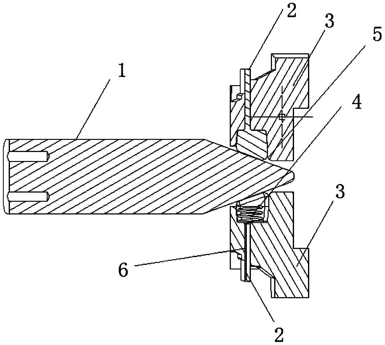
[0027] A kind of mold automatic demoulding structure, its structure sees figure 1 As shown, it is used to realize the demoulding of the mold of the molded part with an undercut structure, the mold includes a movable mold and a solid mold that match each other, and the automatic mold demoulding structure includes being installed in the cavity of the movable mold and following The movable mold pin 1 that moves together is provided with a mounting groove 5 on the base 3 of the solid mold at the position facing the bottom end of the movable mold pin 1 , and the side wall of the mounting groove 5 is processed with an outwardly extending and penetrating The chute 6 of the chute 6 is equipped with a fixed mold sliding block 2 sliding along it, and one end of the fixed mold sliding block 2 located in the installation groove 5 is the inner end, and the other end is the outer end, then the fixed mold sliding block 2 The end face of the inner end of the mold sliding block 2 is processed ...


PUM


Abstract

The invention relates to a mould automatic demoulding structure. The mould automatic demoulding structure comprises a movable mould bolt installed in a mould cavity of a movable mould and moving withthe movable mould, wherein an installation groove is formed in the position, opposite to the bottom end of the movable mould bolt, of a base of a fixed mould, a sliding groove extending outwards and penetrating through is machined on the side wall of the installation groove, a fixed mould sliding block sliding along the sliding groove is mounted in the sliding groove, so that the end, in the installation groove, of the fixed mould sliding block is an inner end and the other end of the fixed mould sliding block is an outer end, the end face of the inner end of the fixed mould sliding block is machined into a slope, and a press elastic piece is arranged between the inner end and the inner wall of a butt joint groove. When the movable mould and the fixed mould are assembled, the movable mouldbolt extrudes the slope of the fixed mould sliding block to enable the fixed mould sliding block to slide outwards until the outer end extends out of the sliding groove and is at the position of theinverted-buckle structure of a part to be molded. Compared with the prior art, the mould automatic demoulding structure does not require personnel to enter the equipment to fetch parts, has safe operation and high demoulding efficiency, and is not easy to damage molded parts.

Description

technical field [0001] The invention belongs to the technical field of high-performance mold manufacturing and relates to an automatic demoulding structure of an EPP mold. Background technique [0002] EPP and other parts that are needed now are designed with an undercut structure for assembly to facilitate fixing. Since these undercuts are not consistent with the demoulding direction in the EPP molding mold, the EPP parts are still buckled in the mold after molding and are difficult to demould. In order to make the molded part break away from the mold, the general method is to force it off or take it out manually by the worker. However, the forceful way is easy to cause the part to be damaged, and the manual removal is not only inefficient but also unsafe. The present invention is proposed in response to the above-mentioned problems. Contents of the invention [0003] The object of the present invention is to provide an automatic mold demoulding structure in order to ov...

Claims


Application Information

Patent Timeline
Patent Type & Authority Patents(China)
IPC IPC(8): B29C45/33B29C45/44
CPCB29C45/33B29C45/44
Inventor 徐瑞亮肖东保
Owner 上海子元汽车零部件有限公司
Learn More