

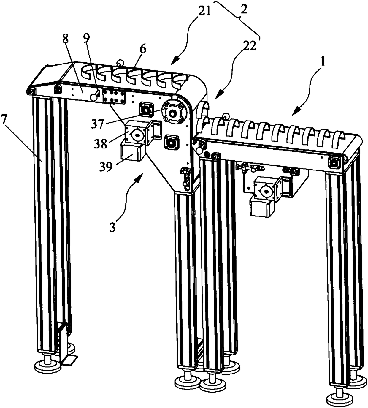
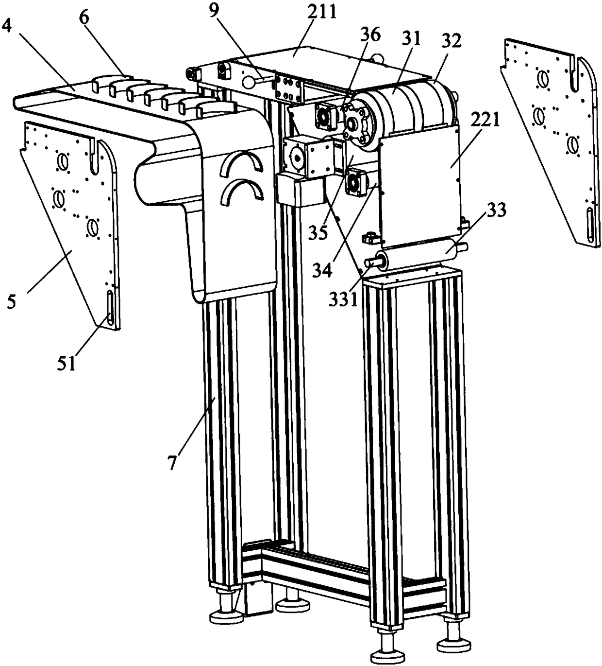
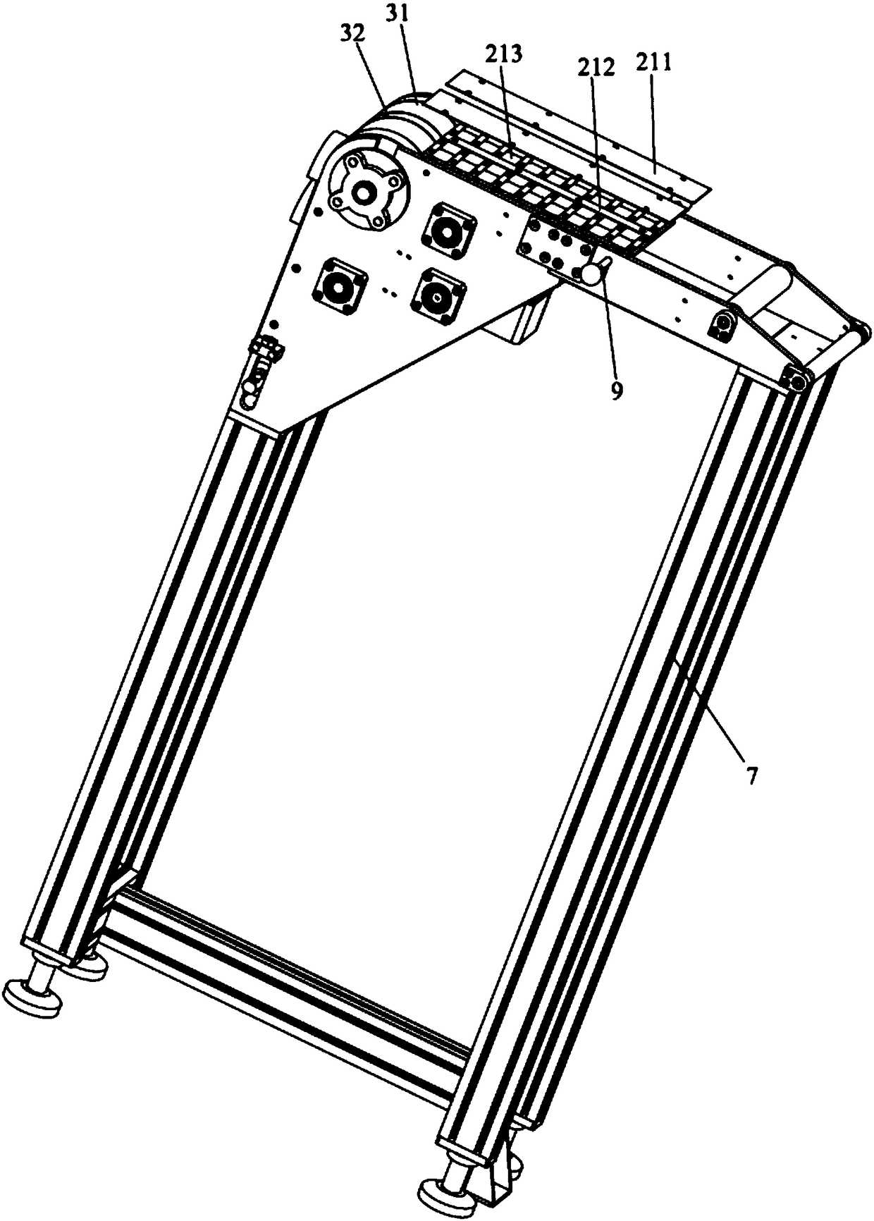
Component conveying device
A technology of conveying device and parts, applied in the field of production line equipment, can solve the problems of unprocessed, increased production line cost, and high manipulator cost, and achieves the effect of simplifying design, saving production cost, and improving production efficiency
- Summary
- Abstract
- Description
- Claims
- Application Information
AI Technical Summary
Problems solved by technology
Method used
Image

Examples
Embodiment Construction
[0029] In order to make the technical problems solved by the present invention, the technical solutions adopted and the technical effects achieved clearer, the technical solutions of the present invention will be further described below in conjunction with the accompanying drawings and through specific implementation methods. It should be understood that the specific embodiments described here are only used to explain the present invention, but not to limit the present invention. In addition, it should be noted that, for the convenience of description, only the parts related to the present invention are shown in the drawings but not all of them.
[0030] At present, on the production line of the workshop, when processing parts, different parts of the parts need to be processed. At this time, the parts need to be turned over. The common technical method is to install a manipulator on the production line, and use the manipulator to turn the parts over to meet the requirements. T...
PUM
 Abstract
Description
Claims
Application Information