Small spray painting cloth unwinding mechanism and use method thereof

A technology of unwinding mechanism and inkjet cloth, which is applied in the direction of winding strips, thin material handling, transportation and packaging, etc. It can solve the problems of affecting the quality of unwinding, stopping of inkjet cloth rolls, and fast unwinding speed of inkjet cloth rolls, etc. , to achieve the effect of ensuring the unwinding quality and stabilizing the unwinding speed

Active Publication Date: 2018-09-18
温岭市锦绣机电有限公司
View PDF5 Cites 6 Cited by
  • Summary
  • Abstract
  • Description
  • Claims
  • Application Information

AI Technical Summary

Problems solved by technology

[0002] The structure of the existing inkjet cloth unwinding mechanism can only stop the pulled out inkjet cloth, but cannot stop the wound inkjet cloth roll, causing the inkjet cloth roll to continue to rotate in a slack state, affecting the unwinding quality; in addition , the unwinding speed of the inkjet cloth roll is too fast, which also has a great impact on the stability of the unwinding, and needs to increase the control device, which is not easy to operate and difficult to meet the needs of production and use. Therefore, we design an inkjet cloth unwinding mechanism. In view of Therefore, we propose a small inkjet cloth unwinding mechanism and its application method

Method used


Image

  • Small spray painting cloth unwinding mechanism and use method thereof
  • Small spray painting cloth unwinding mechanism and use method thereof

Examples


Embodiment Construction

[0020] The following will clearly and completely describe the technical solutions in the embodiments of the present invention with reference to the accompanying drawings in the embodiments of the present invention. Obviously, the described embodiments are only some, not all, embodiments of the present invention. Based on the embodiments of the present invention, all other embodiments obtained by persons of ordinary skill in the art without creative efforts fall within the protection scope of the present invention.

[0021] see Figure 1-2 , the present invention provides a technical solution:

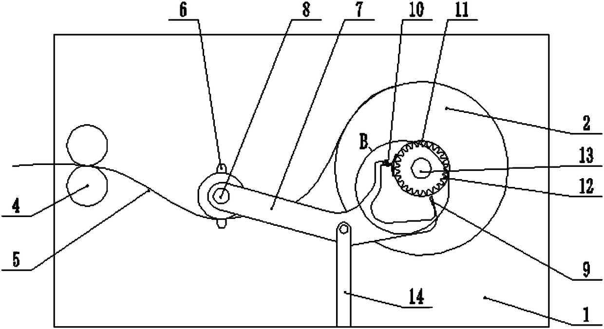
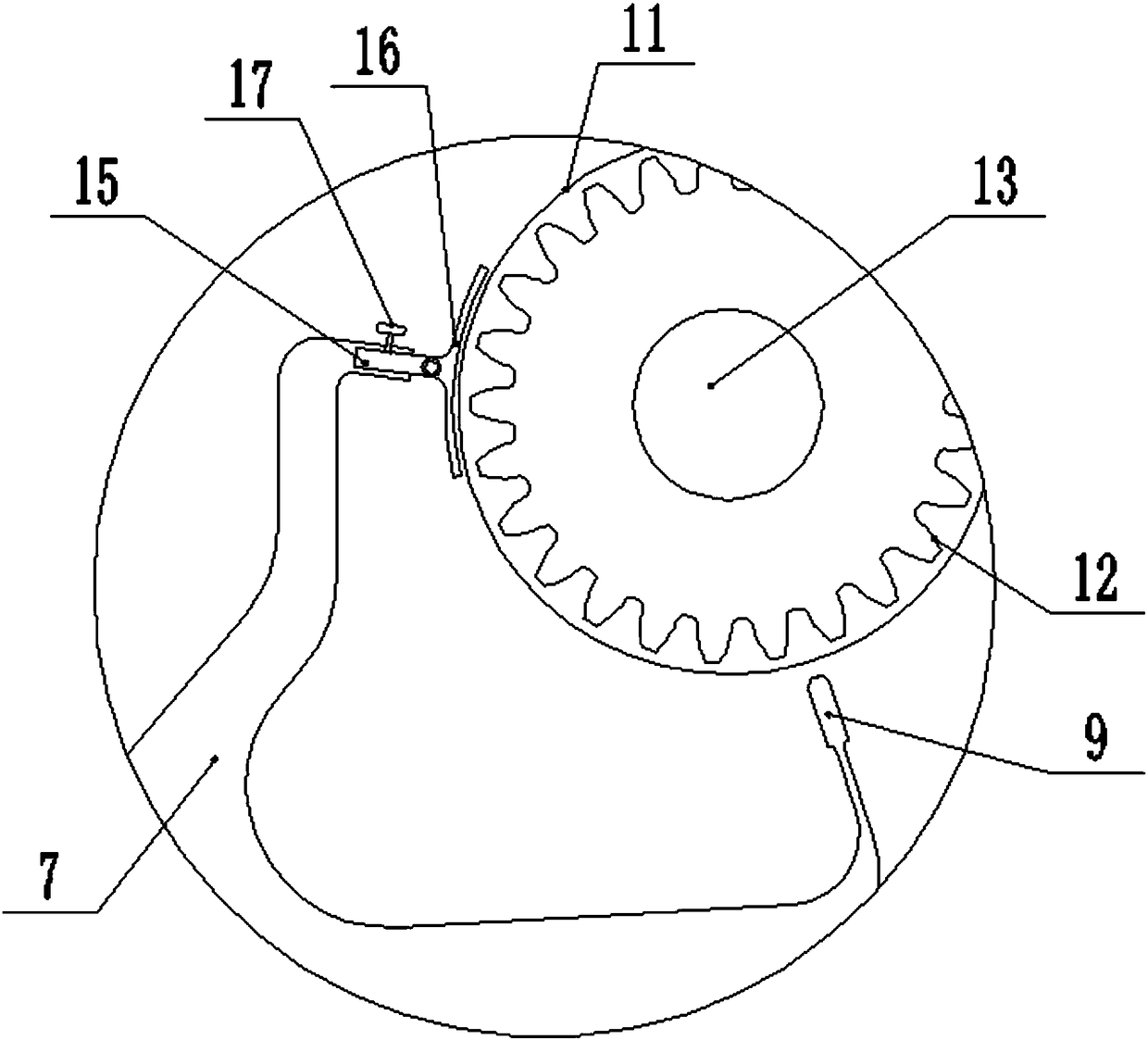
[0022] A small inkjet cloth unwinding mechanism, including an upper pressing wheel 3, a lower pressing wheel 4, and a rotating shaft 13 that are rotatably connected to the two side frame plates 1, the upper pressing plate 3 is located above the lower pressing plate 4, and is closely matched, and the On the rotating shaft 13, there is coaxially fixedly provided with an inkjet cloth roll...


PUM


Abstract

The invention relates to the technical field of glass reinforced plastic pipelines, and specifically discloses a small spray painting cloth unwinding mechanism and a use method thereof. The small spray painting cloth unwinding mechanism comprises an upper pressing wheel, a lower pressing wheel and a rotating shaft. The upper pressing wheel, the lower pressing wheel and the rotating shaft are connected to frame plates on the two sides in a rotating manner. An upper pressing plate is located above a lower pressing plate, and the upper pressing plate and the lower pressing plate are in close cooperation. A spray painting cloth roll is coaxially and fixedly arranged on the rotating shaft. A gear and a friction wheel are coaxially fixed to one end of the rotating shaft. A supporting rod is arranged between the lower pressing wheel and the rotating shaft. The upper end portion of the supporting rod is connected with a lever in a rotating manner. One end of the lever is connected with a balance weight roller in a rotating manner. Slide grooves are formed in the frame plates and correspond to the balance weight roller. A rotating shaft of the balance weight roller is located in the slide grooves and can slide. The other end of the lever is of a forked structure, a tooth block facing the gear is arranged on the end portion of the lower end of a fork, a groove hole is formed in the end portion of the upper end of the fork, and a friction block facing the friction wheel is arranged in the groove hole. By means of the small spray painting cloth unwinding mechanism and the use method, unwinding stability can be improved, and the unwinding speed can be automatically controlled.

Description

technical field [0001] The invention relates to the field of advertisement production, in particular to a small inkjet cloth unwinding mechanism and a using method thereof. Background technique [0002] The structure of the existing inkjet cloth unwinding mechanism can only stop the pulled out inkjet cloth, but cannot stop the wound inkjet cloth roll, causing the inkjet cloth roll to continue to rotate in a slack state, affecting the unwinding quality; in addition , the unwinding speed of the inkjet cloth roll is too fast, which also has a great impact on the stability of the unwinding, and needs to increase the control device, which is not easy to operate and difficult to meet the needs of production and use. Therefore, we design an inkjet cloth unwinding mechanism. In view of Therefore, we propose a small inkjet cloth unwinding mechanism and its application method. Contents of the invention [0003] The purpose of the present invention is to provide a small inkjet cloth...

Claims


Application Information

Patent Timeline
Patent Type & Authority Applications(China)
IPC IPC(8): B65H16/00B65H23/16
CPCB65H16/00B65H23/16B65H2701/19
Inventor 朱锋
Owner 温岭市锦绣机电有限公司
Why Eureka
Try Eureka