
Buffer material mechanism

A technology of cushioning material and frame, which is applied in thin material processing, coiling, transportation and packaging, etc. It can solve the problems of lack of buffer for cutting machines, uneven heating of materials, and white spots caused by slitting and slitting.

Pending Publication Date: 2018-09-18
GUANGDONG ZHENGYE TECH
View PDF4 Cites 0 Cited by
  • Summary
  • Abstract
  • Description
  • Claims
  • Application Information

AI Technical Summary

Problems solved by technology

[0005] The embodiment of the present invention discloses a cushioning material mechanism, which is used to solve the problem that the existing cutting machine lacks buffering in the process of conveying materials, which leads to uneven heating of some materials, resulting in white spots caused by slitting and slitting technical problem

Method used


Image

  • Buffer material mechanism
  • Buffer material mechanism
  • Buffer material mechanism

Examples


Embodiment Construction

[0035] The embodiment of the present invention discloses a cushioning material mechanism, which is used to solve the problem that the existing cutting machine lacks buffering in the process of conveying materials, which leads to uneven heating of some materials and white spots caused by slitting and slitting technical problem.

[0036] In order to enable those skilled in the art to better understand the solution of the present invention, the present invention will be further described in detail below in conjunction with the accompanying drawings and specific embodiments. Apparently, the described embodiments are only some of the embodiments of the present invention, but not all of them. Based on the embodiments of the present invention, all other embodiments obtained by persons of ordinary skill in the art without making creative efforts belong to the protection scope of the present invention.

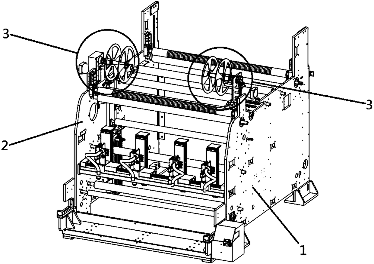
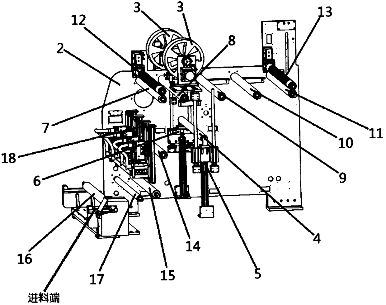
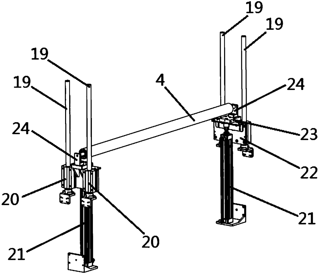
[0037] see Figure 1 to Figure 4 , an embodiment of a buffer mechanism provided ...


PUM


Abstract

The embodiment of the invention discloses a buffer material mechanism. The buffer material mechanism is used for solving the technical problems that a buffer process does not exist in the material conveying process of existing cutting machines, consequently, part of materials are heated unevenly, and white points of straight-cut splits exist. The buffer material mechanism disclosed by the embodiment comprises a first machine frame, a second machine frame and a buffer material device. The buffer material device comprises a charging air swelling shaft, a transition shaft, a first pulling shaft,a third pulling shaft, a fifth pulling shaft, a second pressing roller and a floating roller. The first pulling shaft, the third pulling shaft and the fifth pulling shaft are transversely arranged between a first machine frame and a second machine frame and connected with the first machine frame and the second machine frame. A first end of the floating roller is connected with a first driving assembly. A second end of the floating roller is connected with a second driving assembly. The floating roller is transversely arranged between the first machine frame and the second machine frame and canbe driven to move between the first pulling shaft and the third pulling shaft in the vertical direction.

Description

technical field [0001] The invention relates to the technical field of automation equipment, in particular to a cushioning material mechanism. Background technique [0002] At present, printed circuit boards are widely used, ranging from electronic watches, calculators, mobile phones, general-purpose computers, to computers, communication electronic equipment, and military weapon systems. As long as there are electronic components such as integrated circuits, the electrical interconnection between them must be used on printed circuit boards. Common printed circuit boards and copper clad boards are made of prepregs. [0003] At present, the above-mentioned prepregs are all cut by a cutting machine, and the prepreg rolls are cut into strips and blocks, and the prepreg at the cutting place is heated and then cut using non-contact heating technology. However, the existing The whole process of the material of the cutting machine from feeding to discharging is continuous, withou...

Claims


Application Information

Patent Timeline
Patent Type & Authority Applications(China)
IPC IPC(8): B65H20/30B65H16/06B65H23/26B65H20/02
CPCB65H16/06B65H20/02B65H20/30B65H23/26B65H2701/1133
Inventor 李红利裴同战刘容邹凡
Owner GUANGDONG ZHENGYE TECH
Learn More