New energy automobile elevating mechanism

A new energy vehicle, lifting device technology, applied in the direction of lifting frame, lifting device, lifting equipment safety device, etc., can solve the problem of undisclosed anti-drop protection measures, etc., to achieve the effect of safe use and prevent accidental falling

Inactive Publication Date: 2018-09-18
WUHU SUNYANG INFORMATION CONSULTATION
View PDF5 Cites 5 Cited by
  • Summary
  • Abstract
  • Description
  • Claims
  • Application Information

AI Technical Summary

Problems solved by technology

It can realize the synchronous lifting of the glass plate and solve the problem of deflection of the glass plate during the lifting process, but this kind of lifting mechanism does not disclose the anti-drop protection measures

Method used


Image

  • New energy automobile elevating mechanism
  • New energy automobile elevating mechanism
  • New energy automobile elevating mechanism

Examples


Embodiment 1

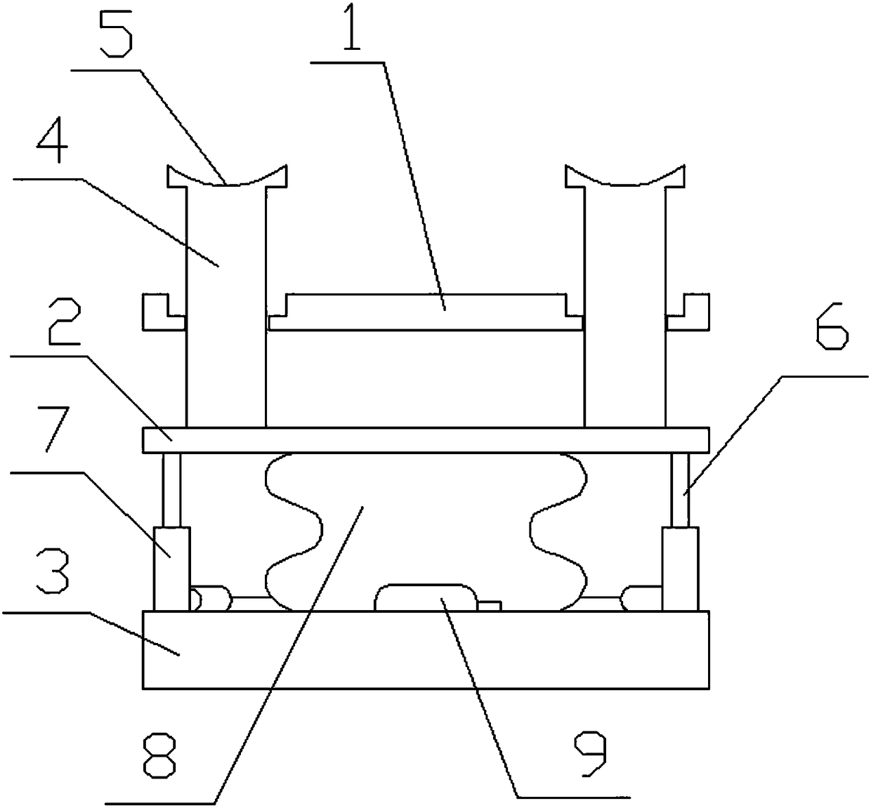
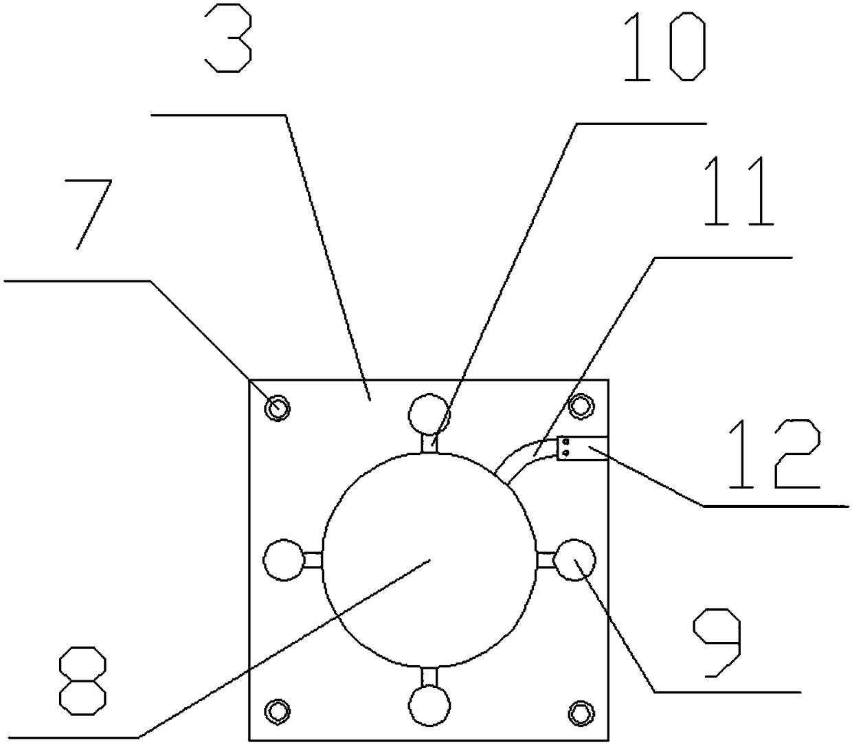
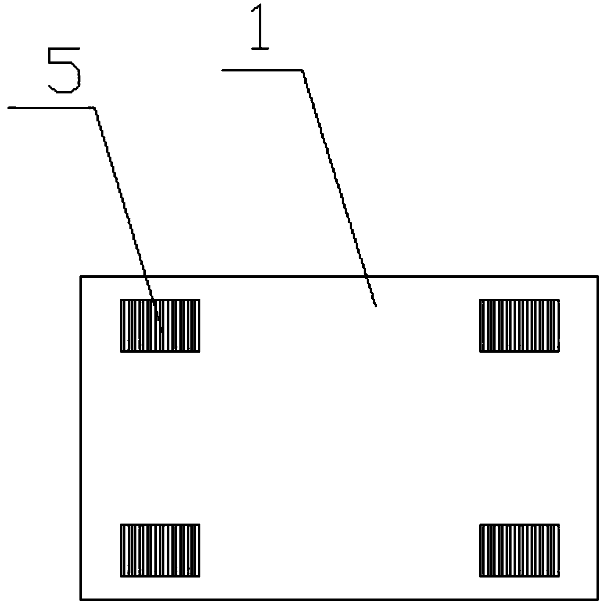
[0020] Such as Figure 1 to Figure 4 As shown, a lifting mechanism for a new energy vehicle includes a limiting plate 1, a lifting plate 2, a positioning plate 3, a lifting device and a limiting device. Keep the stable lifting of the device, the positioning plate 3 can make the device stable, the limiting plate 1 is arranged on the ground, the lifting plate 2 is arranged under the limiting plate 1, and the positioning plate 3 is arranged on the bottom of the lifting plate 2 Below, the upper surface of the lifting plate 2 is provided with four support columns 4 that are slidably connected with the limit plate 1. The support columns 4 play a supporting role and can prevent the vehicle from shaking after the vehicle is lifted. The lifting device is located at Between the lifting plate 2 and the positioning plate 3, the lifting device includes a rubber tube 8, an air pump 9 and an exhaust pipe 11, and the rubber tube 8 is inflated through the air pump 9, so that the rubber tube 8 ...

Embodiment 2

[0026] Such as Figure 1 to Figure 4As shown, a lifting mechanism for a new energy vehicle includes a limiting plate 1, a lifting plate 2, a positioning plate 3, a lifting device and a limiting device. Keep the stable lifting of the device, the positioning plate 3 can make the device stable, the limiting plate 1 is arranged on the ground, the lifting plate 2 is arranged under the limiting plate 1, and the positioning plate 3 is arranged on the bottom of the lifting plate 2 Below, the upper surface of the lifting plate 2 is provided with four support columns 4 that are slidably connected with the limit plate 1. The support columns 4 play a supporting role and can prevent the vehicle from shaking after the vehicle is lifted. The lifting device is located at Between the lifting plate 2 and the positioning plate 3, the lifting device includes a rubber tube 8, an air pump 9 and an exhaust pipe 11, and the rubber tube 8 is inflated through the air pump 9, so that the rubber tube 8 e...


PUM


Abstract

The invention discloses a new energy automobile elevating mechanism, and relates to the field of new energy automobiles. The new energy automobile elevating mechanism comprises a limiting plate, a lifting plate, a positioning plate, an elevating device and a limiting device. The elevating device is arranged between the lifting plate and the positioning plate and comprises a rubber pipe, inflationpumps and an exhaust pipe. The rubber pipe is fixedly connected with the bottom of the lifting plate and the upper end face of the positioning plate. The multiple inflation pumps are arranged and communicate with the rubber pipe through one-way valves. The exhaust pipe is provided with an electronic control valve. The limiting device is arranged in the rubber pipe and comprises a support column fixedly connected with the bottom of the lifting plate and a limiting pipe which is in cup joint to the outer portion of the support column and is fixedly connected with the upper end face of the positioning plate. Inverted teeth are arranged on the support column in the circumferential direction. The top of the limiting pipe is provided with a plurality of inclined hydraulic cylinders. A push rod of each hydraulic cylinder is provided with a triangular limiting block. An infrared speed measuring device is arranged at the connecting position of the limiting pipe and the support column. Accordingto the elevating mechanism, the device can be locked after automobile elevating, and accidents are prevented from happening to the mechanism.

Description

technical field [0001] The invention relates to the field of new energy vehicles, in particular to a lifting mechanism for new energy vehicles. Background technique: [0002] When a new energy vehicle breaks down and needs to be repaired, it is usually repaired in a repair shop. The maintenance workers will use a jack to lift the car slightly and then drill into the bottom of the car for repairs. Due to the limited lifting height of the jack, the hands in the maintenance project The movement will be limited, and if you need to lift the car as a whole, you need to use more jacks, which will take more time and effort, and there is no protection mechanism in the jack, if the jack falls off, there will be an accident occur. [0003] For example, the application number is CN201620356594.4, which discloses a car lifter. The car lifter includes: an oil storage chamber for storing hydraulic oil, a driving oil chamber communicated with the oil storage chamber through a first oil pa...

Claims


Application Information

Patent Timeline
Patent Type & Authority Applications(China)
IPC IPC(8): B66F7/16B66F7/28B66F17/00
CPCB66F7/16B66F7/28B66F17/006
Inventor 赵文娟赵文波
Owner WUHU SUNYANG INFORMATION CONSULTATION
Why Eureka
Try Eureka