
Knife switch type electric energy metering combined conjunction box

A combined junction box and electric energy metering technology, applied in the direction of measuring electrical variables, measuring devices, measuring time integration, etc., can solve problems such as difficult to control the quality of installation process, affect fault judgment, and be prone to misunderstanding, so as to achieve enhanced practicability, Improved quality and high safety effects

Inactive Publication Date: 2018-09-18
SHANGHAI UNIVERSITY OF ELECTRIC POWER
View PDF5 Cites 2 Cited by
  • Summary
  • Abstract
  • Description
  • Claims
  • Application Information

AI Technical Summary

Problems solved by technology

In the paper "Brief Introduction to the Correct Use of Electric Energy Metering Joint Junction Box", it is clarified that the existing electric energy metering joint junction box mainly realizes the switching between the working and disconnecting states of the junction box by connecting and disconnecting different terminals. Such a combined electrical energy metering junction box is extremely easy to be misunderstood when connecting, and there are too many contacts inside such a junction box. Not only are there many operating procedures, but also the installation process quality is difficult to control. poor
[0004] In addition, the current joint junction box for electric energy measurement is generally made of black opaque material. The joint junction box for electric energy measurement realized in this way is easy to affect the fault judgment and the detection of electricity theft and leakage

Method used


Image

  • Knife switch type electric energy metering combined conjunction box
  • Knife switch type electric energy metering combined conjunction box
  • Knife switch type electric energy metering combined conjunction box

Examples


Embodiment Construction

[0032] The present invention will be described in detail below in conjunction with the accompanying drawings and specific embodiments. This embodiment is carried out on the premise of the technical solution of the present invention, and detailed implementation and specific operation process are given, but the protection scope of the present invention is not limited to the following embodiments.

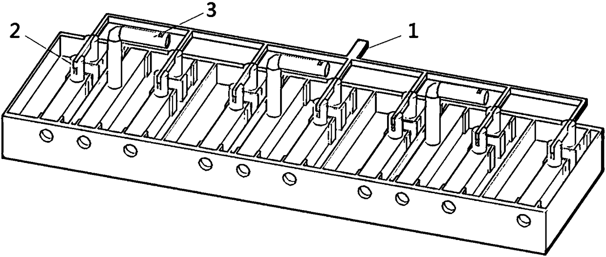
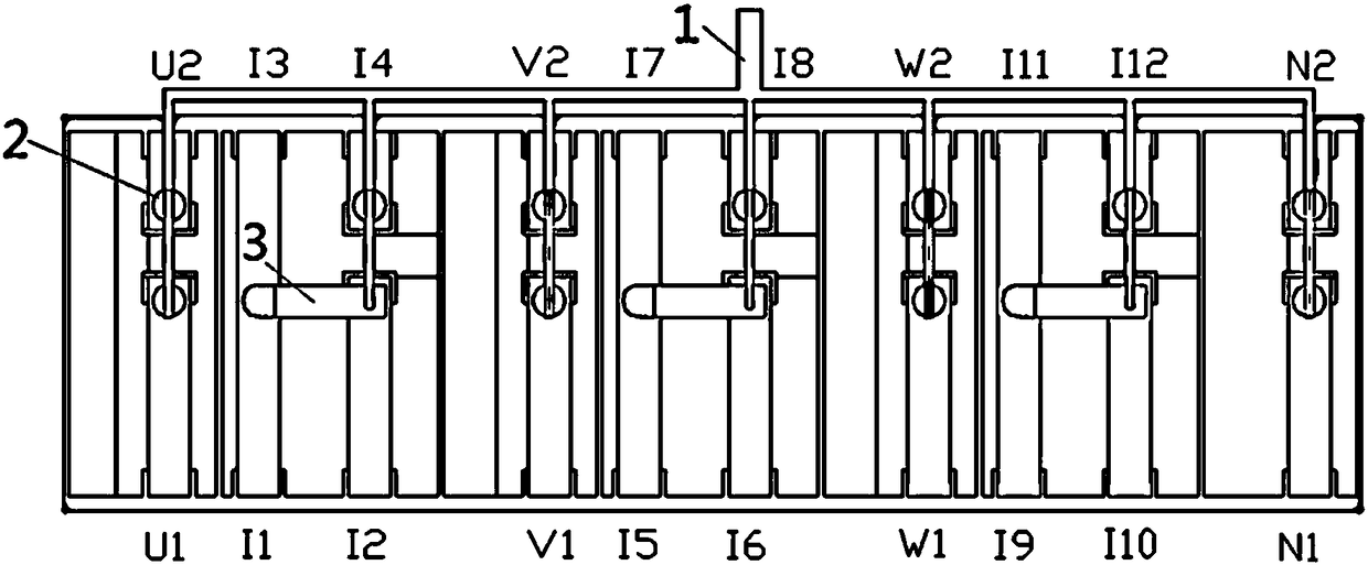
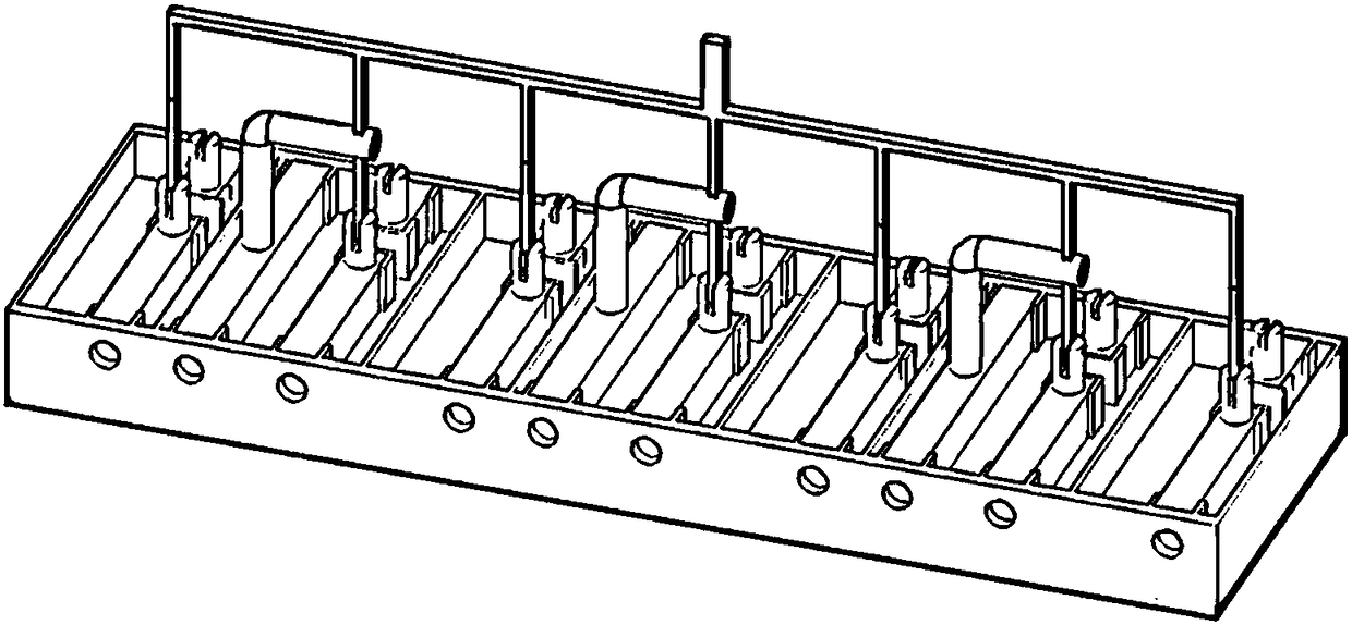
[0033] This embodiment provides a combined junction box for switch knife type electric energy metering, which includes a box body, on which a plurality of different terminals are provided, respectively connected to the voltage on the power supply side, the current on the power supply side, the voltage transformer and the current transformer Connection, the combined junction box of the knife-type electric energy metering also includes an on-off connection module and a knife switch 1, the first end of the knife switch 1 is fixed inside the box body through the on-off connection module, a...


PUM


Abstract

The invention relates to a knife switch type electric energy metering combined conjunction box which comprises a box body. The box body is provided with a plurality of different terminals which are respectively connected with power-supply-side voltage, power-supply-side current, a voltage transformer and a current transformer. The knife switch type electric energy metering combined conjunction boxfurther comprises an on-off connecting module and a knife switch. The first end of the knife switch is fixed in the box body through the on-off connecting module. The second end of the knife switch rotates around the first end. When the knife switch rotates to a position which is coplanar with the box body, the on-off connecting module is on, the knife switch type electric energy metering combined conjunction box is in a working state. When the knife switch is rotated to be perpendicular with the box body, the on-off connecting module is off, and the knife switch type electric energy meteringcombined conjunction box is in an off state. Compared with prior art, the knife switch type electric energy metering combined conjunction box has advantages of no frequent wiring error, easy operation, easy maintenance, high practicability, etc.

Description

technical field [0001] The invention relates to the field of electric energy metering devices, in particular to a switch knife type combined junction box for electric energy metering. Background technique [0002] The combined junction box for electric energy measurement is also the test terminal referred to in the inspection regulations for electric energy metering devices. The combined junction box for electric energy measurement can reduce the number of TA (current transformer) and TV (voltage transformer), which is convenient for live calibration of measuring instruments, and The connected instrument can be exchanged under electrified condition without affecting the normal operation of other instruments. The joint junction box plays a pivotal role in the electrical measurement circuit, and can effectively prevent wiring errors and improve measurement accuracy. It has multiple functions and has been widely used. [0003] With the popularization and use of junction boxes ...

Claims


Application Information

Patent Timeline
Patent Type & Authority Applications(China)
IPC IPC(8): G01R11/04
CPCG01R11/04
Inventor 刘建锋黄世龙张科曌
Owner SHANGHAI UNIVERSITY OF ELECTRIC POWER
Learn More