RFID antenna, RFID label and RFID antenna manufacturing method

A production method and antenna technology, applied to antennas, antenna parts, antenna grounding devices, etc., can solve the problems of high cost of RFID antennas, achieve huge economic and social benefits, good stability, and the effect of energy saving and emission reduction according to market demand

Pending Publication Date: 2018-09-18
SHENZHEN ZHENHUA MICROELECTRONICS
View PDF12 Cites 0 Cited by
  • Summary
  • Abstract
  • Description
  • Claims
  • Application Information

AI Technical Summary

Problems solved by technology

Make the whole RFID antenna cost higher

Method used


Image

  • RFID antenna, RFID label and RFID antenna manufacturing method
  • RFID antenna, RFID label and RFID antenna manufacturing method
  • RFID antenna, RFID label and RFID antenna manufacturing method

Examples


Embodiment Construction

[0038] In order to have a clearer understanding of the technical features, purposes and effects of the present invention, the specific implementation manners of the present invention will now be described in detail with reference to the accompanying drawings.

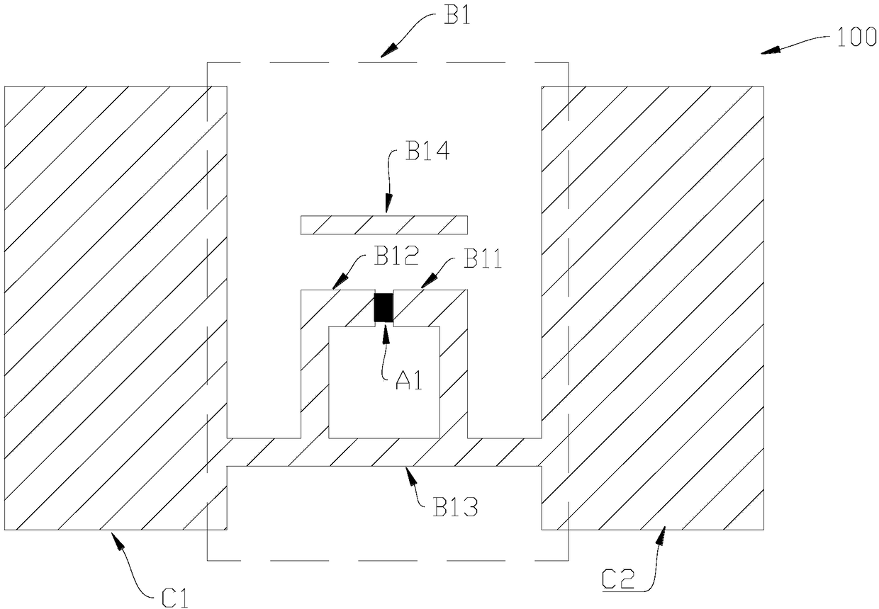
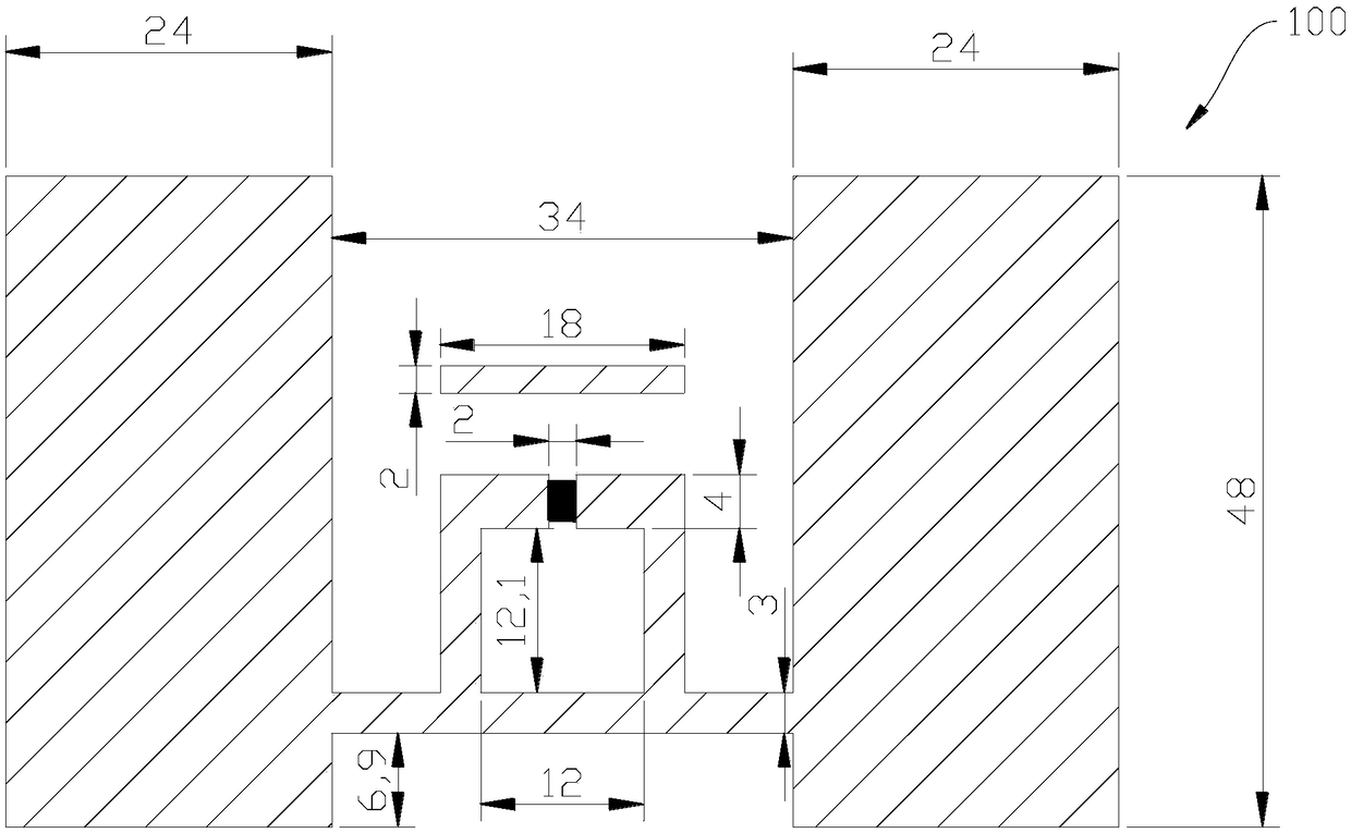
[0039] A kind of RFID antenna of the present invention, its slurry is nickel slurry, wherein nickel slurry satisfies: viscosity between 85Pa s-115Pa s, linear resolution less than 200μm, resistivity less than 80mΩ / Sq, adhesion greater than or equal to 625N / cm 2 . Specifically, the existing RFID antenna is usually made by printing conductive paste on the substrate. In the present invention, the RFID antenna adopts nickel paste that meets the requirements on the ceramic substrate (nickel paste constitutes the antenna body), and then sinters it. Here Different proportions of nickel can be selected to debug a suitable nickel paste. Compared with the silver conductive paste that needs to print a sintered protective layer (...


PUM


Abstract

The invention relates to an RFID antenna, an RFID label and an RFID antenna manufacturing method, wherein the slurry of the RFID antenna is nickel slurry. The nickel slurry satisfies the conditions described as follows: viscosity is 85-115Pa*s; linear resolution is lower than 200 [mu]m; resistivity is lower than 80 m[omega]/Sq; and an adhesion force is higher than or equal with 625N/cm<2>. The RFID antenna, the RFID label and the RFID antenna manufacturing method have advantages of reducing RFID antenna cost, saving energy and reducing emission.

Description

technical field [0001] The invention relates to the field of antennas, and more specifically, to an RFID antenna, an RFID tag and a manufacturing method for the RFID antenna. Background technique [0002] Radio Frequency Identification (RFID) is an advanced form of automatic identification technology. As an advanced automatic identification technology, RFID has the advantages of large storage capacity, readable and writable, long recognition distance, fast recognition speed and long service life. , good environmental adaptability and simultaneous identification of multiple tags can be widely used in supply chain management, transportation management, industrial production management, animal identification management, access control, anti-counterfeiting, anti-theft, logistics, sports timing and other occasions . [0003] With the rapid development of the global Internet of Things, the annual demand for RFID tags will be in the hundreds of millions, and the low cost of RFID t...

Claims


Application Information

Patent Timeline
Patent Type & Authority Applications(China)
IPC IPC(8): H01Q1/22H01Q1/36H01Q1/48H01Q1/50G06K19/067
CPCH01Q1/2225H01Q1/36H01Q1/48H01Q1/50G06K19/067
Inventor 涂小军赵袆文莉贵
Owner SHENZHEN ZHENHUA MICROELECTRONICS
Why Eureka
Try Eureka