Method for suppressing vibration of built-in permanent magnet motor and improving torque performance
A permanent magnet motor, built-in technology, applied in the direction of magnetic circuit rotating parts, magnetic circuit static parts, magnetic circuit shape/style/structure, etc. Cogging torque and other problems, to achieve the effect of improving performance, suppressing amplitude, and reducing cogging torque
- Summary
- Abstract
- Description
- Claims
- Application Information
AI Technical Summary
Problems solved by technology
Method used
Image
Examples
Embodiment 1
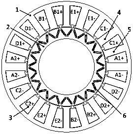
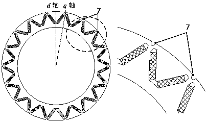
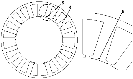
[0034] In this embodiment, the rotor q Auxiliary grooves are opened at the shaft position, in figure 1 Auxiliary grooves are provided on the stator armature teeth shown to obtain the stator structure of this embodiment, as shown in Figure 3-1 shown.
[0035] Since the auxiliary grooves are provided on the stator armature teeth in this embodiment, the number of equivalent slots on the inner surface of the stator is changed to a certain extent, thereby changing the harmonics of the stator magnetic conduction teeth and reducing the first-order harmonics of the stator teeth , and finally reduce the amplitude of the second-order electromagnetic force harmonic of the motor.
Embodiment 2
[0037] This embodiment maintains the rotor q The structure of the auxiliary groove at the shaft position remains unchanged. figure 1 Auxiliary grooves are provided on the fault-tolerant teeth of the stator shown, and the stator structure of this embodiment is obtained, as shown in Figure 3-2 shown.
[0038] Since the auxiliary grooves are provided on the stator armature teeth in this embodiment, the number of equivalent slots on the inner surface of the stator is changed to a certain extent, thereby changing the harmonics of the stator magnetic conduction teeth and reducing the first-order harmonics of the stator teeth , and finally reduce the amplitude of the second-order electromagnetic force harmonic of the motor.
Embodiment 3
[0040] This embodiment maintains the rotor q The structure of the auxiliary groove at the shaft position remains unchanged. figure 1 The shown stator armature teeth and fault-tolerant teeth are provided with auxiliary grooves to obtain the stator structure of this embodiment, as shown in Figure 3-3 shown.
[0041] Since the auxiliary grooves are provided on the stator armature teeth in this embodiment, the number of equivalent slots on the inner surface of the stator is changed to a certain extent, thereby changing the harmonics of the stator magnetic conduction teeth and reducing the first-order harmonics of the stator teeth , and finally reduce the amplitude of the second-order electromagnetic force harmonic of the motor.
[0042] Figure 4 It is a comparison diagram of the cogging torque of the motors of the above three embodiments obtained through finite element simulation and the cogging torque of the original motor. Compared with the cogging torque of the original m...
PUM
 Abstract
Description
Claims
Application Information
 - R&D
- Intellectual Property
- Life Sciences
- Materials
- Tech Scout
- Unparalleled Data Quality
- Higher Quality Content
- 60% Fewer Hallucinations
Browse by: Latest US Patents, China's latest patents, Technical Efficacy Thesaurus, Application Domain, Technology Topic, Popular Technical Reports.
© 2025 PatSnap. All rights reserved.Legal|Privacy policy|Modern Slavery Act Transparency Statement|Sitemap|About US| Contact US: help@patsnap.com


